Your fzp file has errors which will kill it. It lacks a moduleId for starters
<?xml version='1.0' encoding='UTF-8' standalone='no'?>
<module fritzingVersion="0.9.3b">
needs to look like
<module fritzingVersion="0.9.3b" moduleId="linear-actuator_1">
the moduleId needs to be unique so you may want to use parts editor to create a part from a 2 position header to let it make a correctly formatted file to modify with a correct and unique moduleId (it is also possible to make one from scratch if you know what it needs to look like and are careful to make it unique in the current core parts.) Then you are missing icon view
  <views>
    <breadboardView>
      <layers image="breadboard/linear-actuator_1_breadboard.svg">
        <layer layerId="breadboard"/>
      </layers>
    </breadboardView>
    <schematicView>
      <layers image="schematic/linear-actuator_1_schematic.svg">
        <layer layerId="schematic"/>
      </layers>
    </schematicView>
    <pcbView>
      <layers image="pcb/linear-actuator_1_pcb.svg">
        <layer layerId="copper0"/>
        <layer layerId="copper1"/>
        <layer layerId="silkscreen"/>
      </layers>
    </pcbView>
  </views>
which needs to look like this
  <views>
    <iconView>
      <layers image="breadboard/fc-51_breadboard.svg">
        <layer layerId="icon"/>
      </layers>
    </iconView>
    <breadboardView>
      <layers image="breadboard/fc-51_breadboard.svg">
        <layer layerId="breadboard"/>
      </layers>
    </breadboardView>
    <schematicView>
      <layers image="schematic/fc-51_schematic.svg">
        <layer layerId="schematic"/>
      </layers>
    </schematicView>
    <pcbView>
      <layers image="pcb/fc-51_pcb.svg">
        <layer layerId="silkscreen"/>
        <layer layerId="copper0"/>
        <layer layerId="copper1"/>
      </layers>
    </pcbView>
  </views>
(here I replaced the icon svg file with the breadboard file, although you can have a separate icon file if you like.) I’m not sure a missing icon view will be fatal but it may be. The connector definitions need a name field
  <connectors>
    <connector id="connector0" type="male">
      <description>Connector 0</description>
      <views>
        <breadboardView>
          <p svgId="connector0pin" layer="breadboard"/>
        </breadboardView>
        <schematicView>
          <p svgId="connector0terminal" layer="schematic"/>
        </schematicView>
        <pcbView>
          <p svgId="connector0pin" layer="copper0"/>
          <p svgId="connector0pin" layer="copper1"/>
        </pcbView>
      </views>
    </connector>
needs to look like
  <connectors>
    <connector id="connector0" name="pin0" type="male">
      <description>Connector 0</description>
      <views>
        <breadboardView>
          <p svgId="connector0pin" layer="breadboard"/>
        </breadboardView>
        <schematicView>
          <p svgId="connector0terminal" layer="schematic"/>
        </schematicView>
        <pcbView>
          <p svgId="connector0pin" layer="copper0"/>
          <p svgId="connector0pin" layer="copper1"/>
        </pcbView>
      </views>
    </connector>
easiest to start from a two pin connector part and modify the supplied svgs which will have the correct values. Then I ran the corrected part through FritzingCheckPart.py which produces this output:
$ FritzingCheckPartw.py part.linear-actuator_12v_aldrin-inbaraj_1.fzp
**** Starting to process file Startup, no file yet
**** Starting to process file part.linear-actuator_12v_aldrin-inbaraj_1.fzp
**** Starting to process file svg.breadboard.linear-actuator_1_breadboard.svg.bak
**** Starting to process file svg.schematic.linear-actuator_1_schematic.svg.bak
**** Starting to process file svg.pcb.linear-actuator_1_pcb.svg.bak
File
‘part.linear-actuator_12v_aldrin-inbaraj_1.fzp.bak’
This is a through hole part as both copper0 and copper1 views are present.
If you wanted a smd part remove the copper0 definition from line 28
Modified 7: File
‘svg.schematic.linear-actuator_1_schematic.svg.bak’
At line 20
A Tspan was removed.
Check the output svg is correctly formatted after the change.
Warning 4: File
‘part.linear-actuator_12v_aldrin-inbaraj_1.fzp.bak’
At line 2
No referenceFile found in fzp file
Warning 9: File
‘part.linear-actuator_12v_aldrin-inbaraj_1.fzp.bak’
One or more expected views missing (may be intended)
Warning 14: File
‘part.linear-actuator_12v_aldrin-inbaraj_1.fzp.bak’
At line 42
terminalId missing in schematicView (likely an error)
Warning 14: File
‘part.linear-actuator_12v_aldrin-inbaraj_1.fzp.bak’
At line 57
terminalId missing in schematicView (likely an error)
Warning 18: File
‘svg.breadboard.linear-actuator_1_breadboard.svg.bak’
At line 6
Height attribute missing
Warning 18: File
‘svg.breadboard.linear-actuator_1_breadboard.svg.bak’
At line 6
Width attribute missing
Warning 18: File
‘svg.schematic.linear-actuator_1_schematic.svg.bak’
At line 6
Height attribute missing
Warning 18: File
‘svg.schematic.linear-actuator_1_schematic.svg.bak’
At line 6
Width attribute missing
Warning 18: File
‘svg.pcb.linear-actuator_1_pcb.svg.bak’
At line 5
Height attribute missing
Warning 18: File
‘svg.pcb.linear-actuator_1_pcb.svg.bak’
At line 5
Width attribute missing
Warning 25: File
‘svg.pcb.linear-actuator_1_pcb.svg.bak’
At line 20
Silkscreen layer should be above the copper layers for easier selection
in pcb view
Warning 27: File
‘svg.pcb.linear-actuator_1_pcb.svg.bak’
At line 20
Fritzing layerId silkscreen isn’t a group which it usually should be
Error 22: File
‘part.linear-actuator_12v_aldrin-inbaraj_1.fzp.bak’
At line 2
No ModuleId found in fzp file
Error 91: File
‘svg.schematic.linear-actuator_1_schematic.svg.bak’
At line 20
Tspan removal error, TspanText already has text
'Linear ’
in it.
Error 94: File
‘svg.schematic.linear-actuator_1_schematic.svg.bak’
The svg has been modified (details in the Modified section).
Examine the svg with a svg editor to make sure it is correctly formatted.
In general version 0.9.3b doesn’t support tspans so checkpart attempts to remove them (later versions may no longer have this limitation I haven’t checked lately.) So this will need manual correction. The
Warning 14: File
‘part.linear-actuator_12v_aldrin-inbaraj_1.fzp.bak’
At line 42
terminalId missing in schematicView (likely an error)
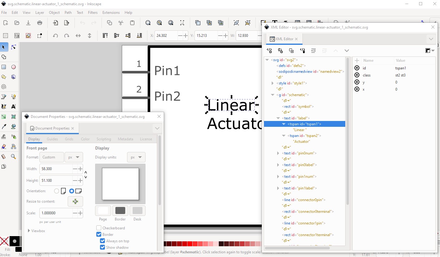
as well your svgs are incorrectly configured. Dimensions are set to px which causes Fritzing to guess at the dpi setting (which it often gets wrong!) which can cause scaling issues (when it guesses wrong.) As well your svgs are not correctly configured. They lack height and width settings in the metadata which may be causing problems (for instance breadboard won’t load in Fritzing which led me here)
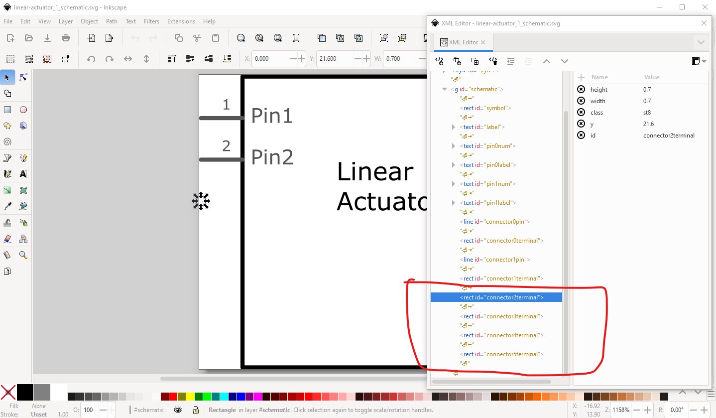
I manually removed this tspan in schematic and correced some other problems like this
means your fzp file is without a terminalId which causes this error in schematic (and why it is marked as usually an error.) The terminalId is present in the svg (although it wasn’t quite correct.) I changed the dimensions from px to in (which will likely make the scale wrong but I didn’t correct that because it isn’t vital for this.) Instead I manually corrected the pin spacing which is the only important part here.
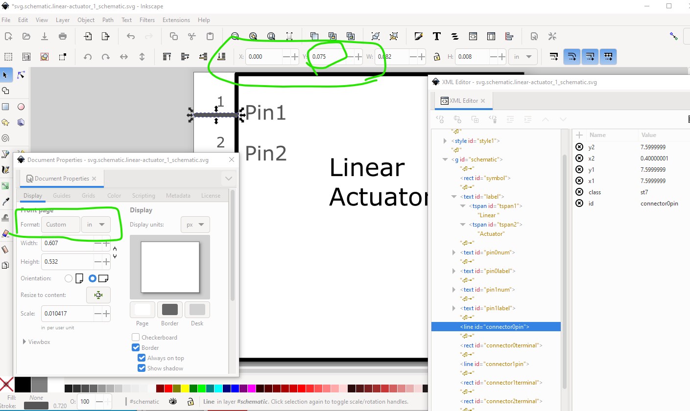
Here connector0pin is at y coord 0.075in that means connector1pin needs to be at 0.175in (but is currently not!) to be on the 0.1in grid that is standard in schematic.
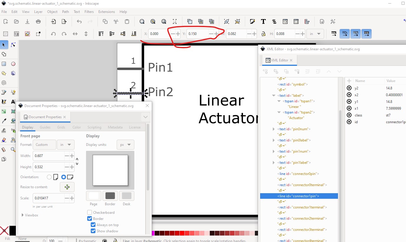
connector1pin is at 0.150in which will put it off the grid. So change it (and its associated terminatlId) tobe at 0.175in.
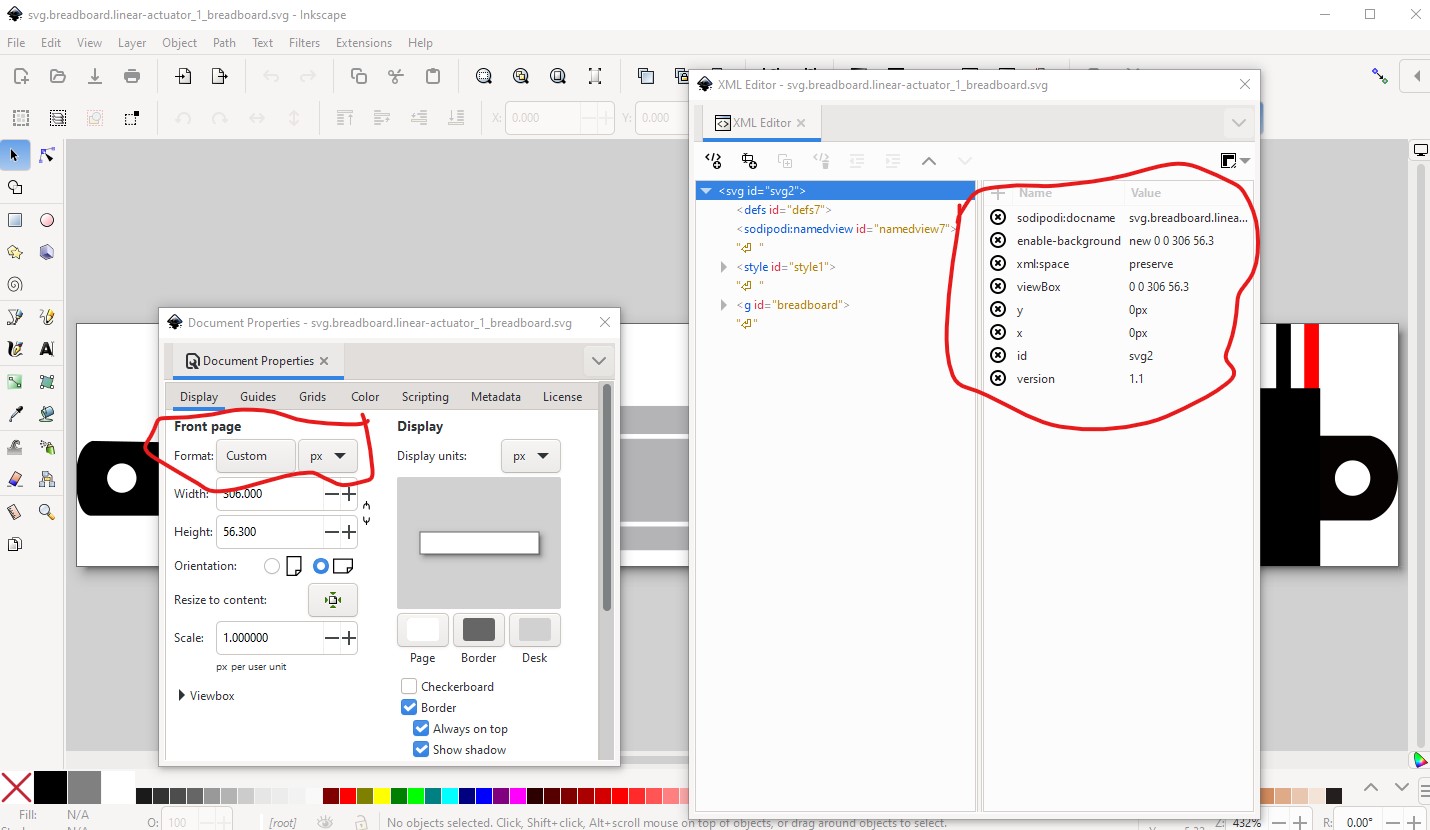
The breadboard svg has similar problems. It is set to px (scaling problems) and lacks the height and width settings in the metadata.
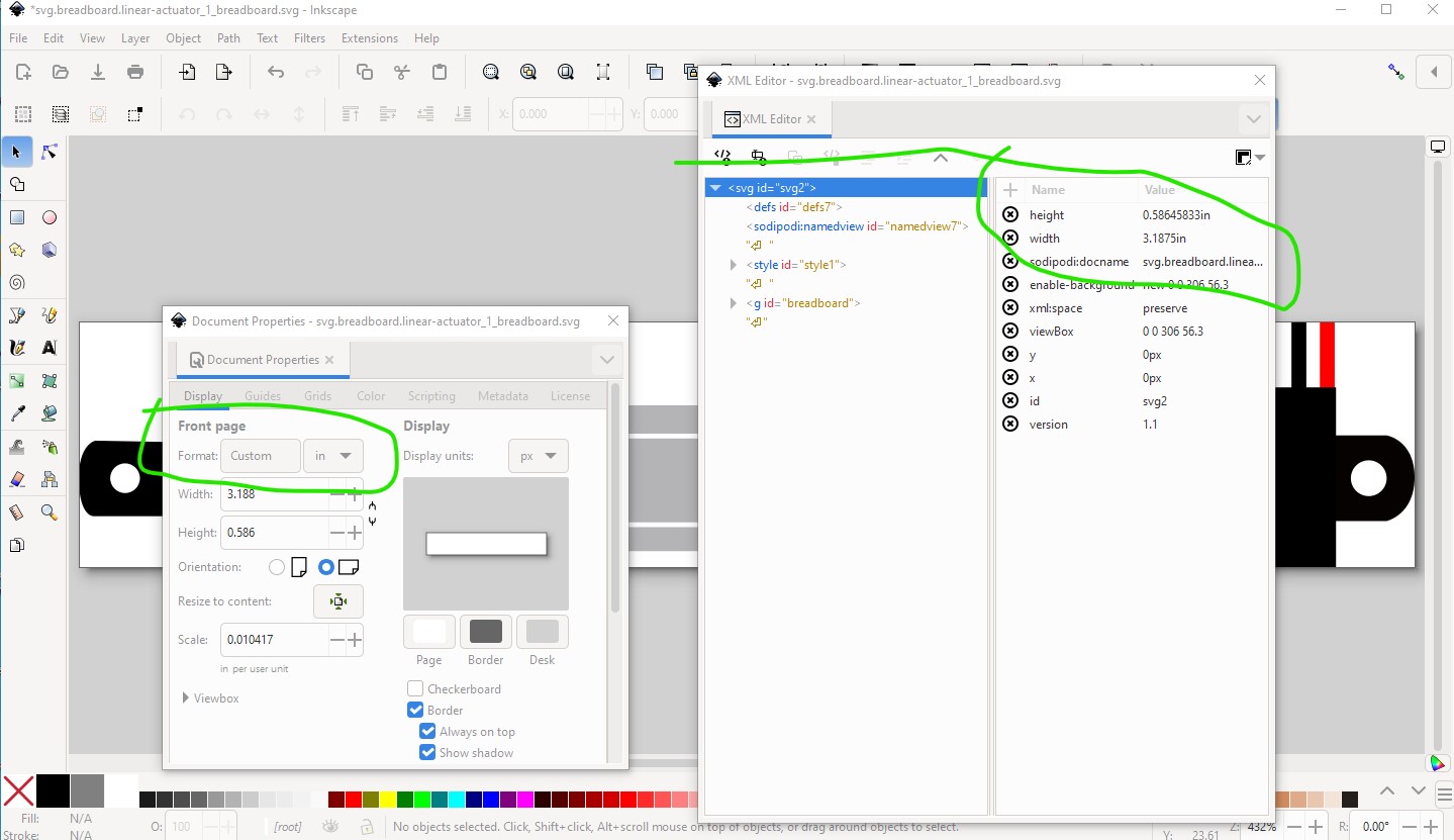
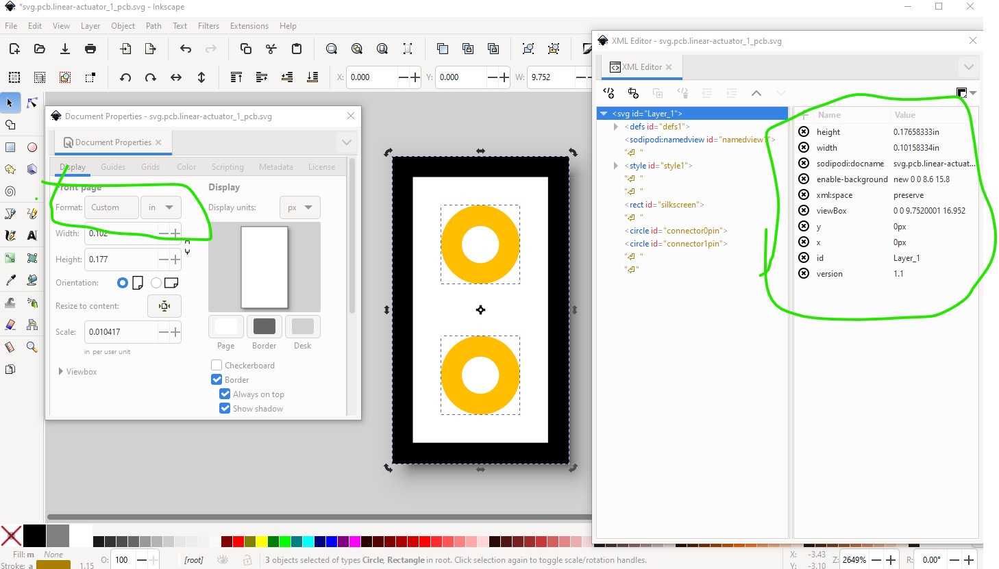
Edit the svg with Inscape and set the Format to in which recreates the metadata and adds the missing height and width attributes
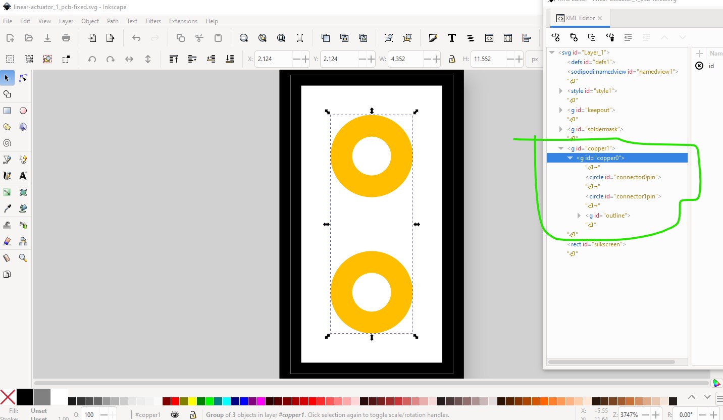
pcb has more errors
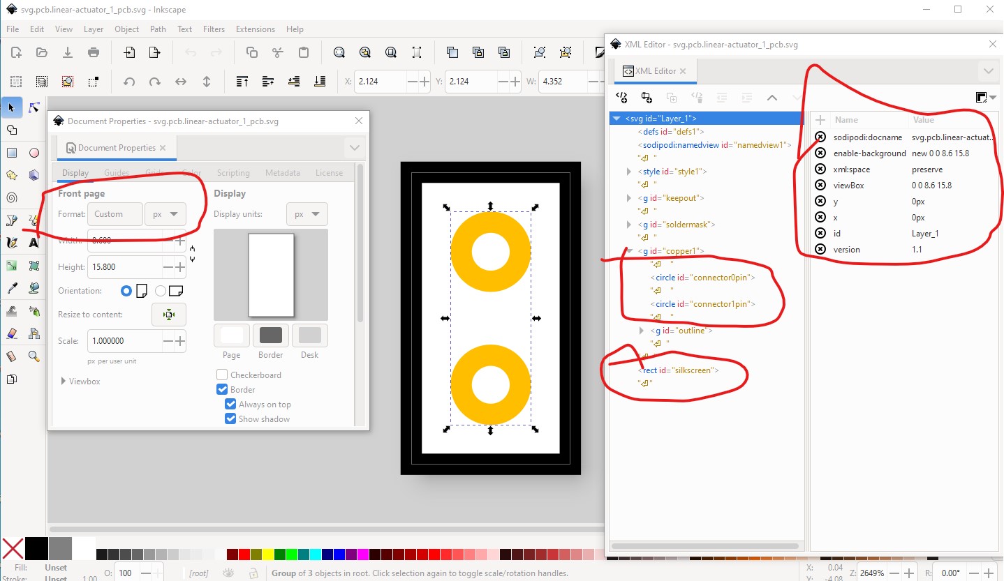
it is dimensioned in px, has no height or width attributes, and silkscreen is not a group as it needs to be to work. So ungroup all the groups (which are incorrect anyway) change it to in and resize it to set the metadata.
now correct the scale so the pads are 0.1in apart.
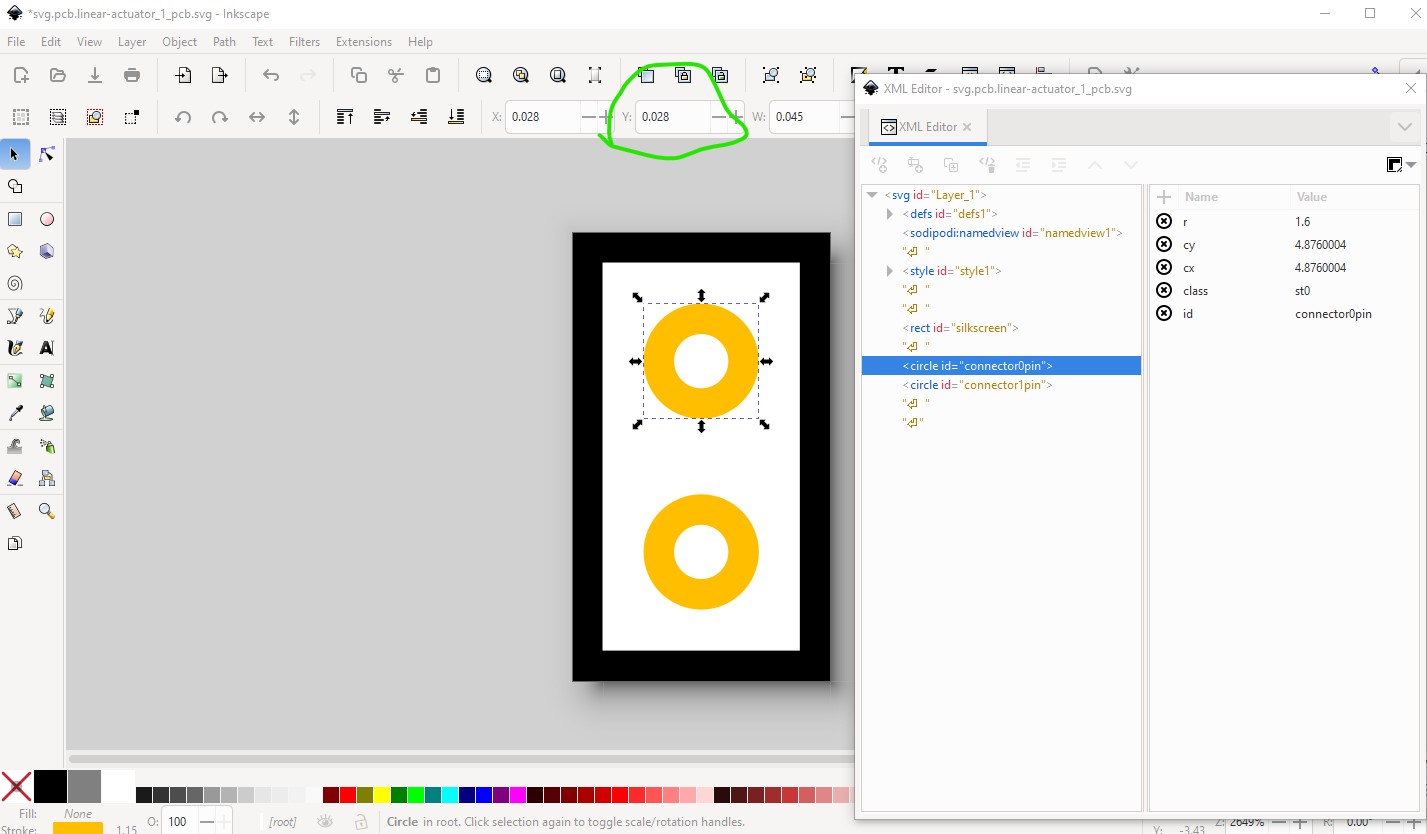
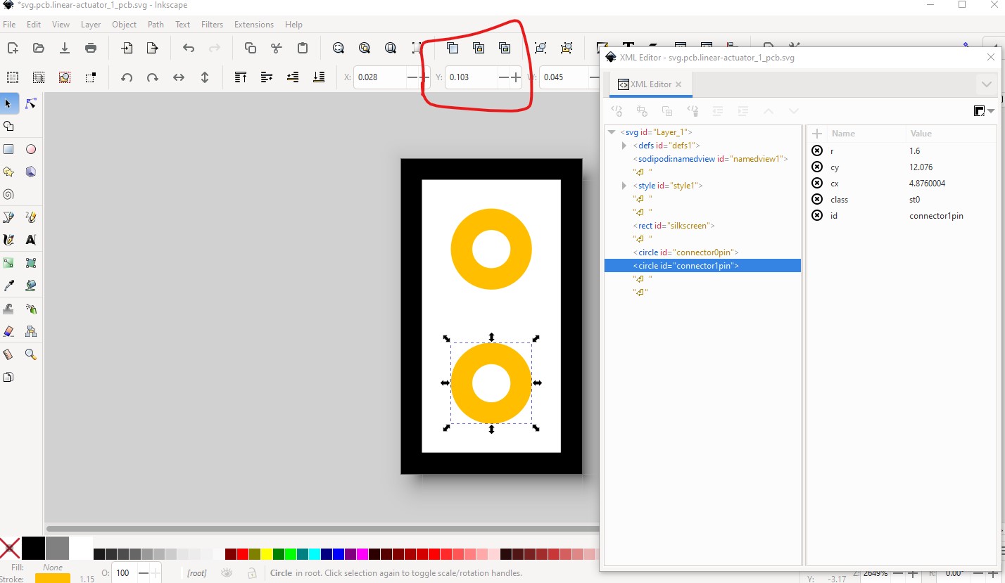
connector0 is at 0.028in in Y so connector1 needs to be at 0.128in not the 0.103in it is at present.
As well the height of the silkscreen rectangle needs to increase.
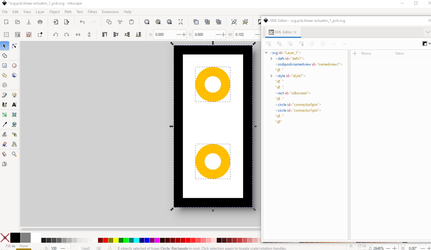
then we need to add the groups
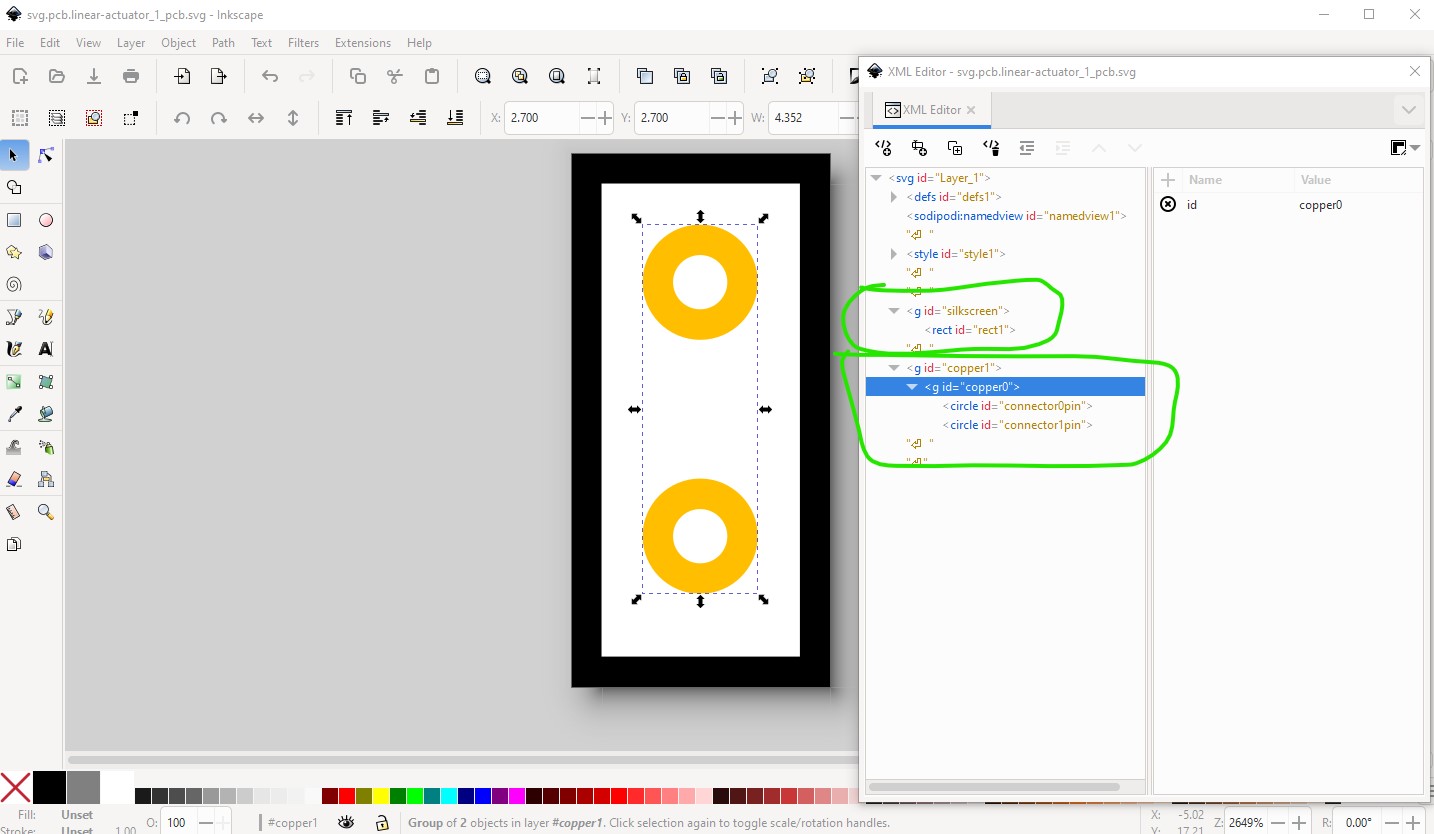
silkscreen needs to be a group (not the label on the rectangle) and copper0 needs to be a child of copper1 as this is a through hole part. With that all done FritzingCheckPart is much happier:
$ FritzingCheckPartw.py part.linear-actuator_12v_aldrin-inbaraj_1.fzp
**** Starting to process file Startup, no file yet
**** Starting to process file part.linear-actuator_12v_aldrin-inbaraj_1.fzp
**** Starting to process file svg.breadboard.linear-actuator_1_breadboard.svg.bak
**** Starting to process file svg.schematic.linear-actuator_1_schematic.svg.bak
**** Starting to process file svg.pcb.linear-actuator_1_pcb.svg.bak
File
‘part.linear-actuator_12v_aldrin-inbaraj_1.fzp.bak’
This is a through hole part as both copper0 and copper1 views are present.
If you wanted a smd part remove the copper0 definition from line 33
Warning 3: File
‘part.linear-actuator_12v_aldrin-inbaraj_1.fzp.bak’
At line 2
ModuleId ‘linear-actuator_1’
Doesn’t match filename
‘linear-actuator_12v_aldrin-inbaraj_1’
Warning 4: File
‘part.linear-actuator_12v_aldrin-inbaraj_1.fzp.bak’
At line 2
No referenceFile found in fzp file
Warning 14: File
‘part.linear-actuator_12v_aldrin-inbaraj_1.fzp.bak’
At line 47
terminalId missing in schematicView (likely an error)
Warning 14: File
‘part.linear-actuator_12v_aldrin-inbaraj_1.fzp.bak’
At line 62
terminalId missing in schematicView (likely an error)
Warning 32: File
‘svg.breadboard.linear-actuator_1_breadboard.svg.bak’
At line 14
Scale is not the desirable 1/1000 ratio from width/height to
viewBox width/height.
Warning 32: File
‘svg.schematic.linear-actuator_1_schematic.svg.bak’
At line 13
Scale is not the desirable 1/1000 ratio from width/height to
viewBox width/height.
Warning 32: File
‘svg.pcb.linear-actuator_1_pcb.svg.bak’
At line 15
Scale is not the desirable 1/1000 ratio from width/height to
viewBox width/height.
These changes create a part that loads in Fritzing (but still has problems!)
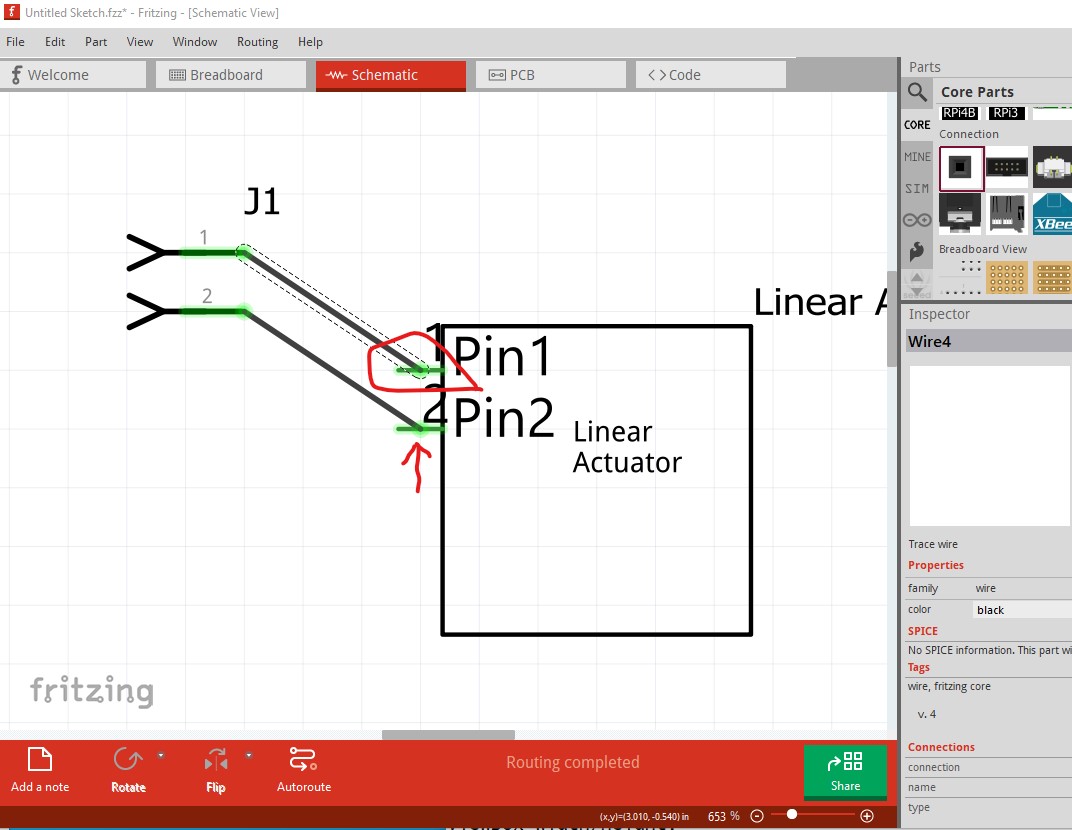
Here I changed the .fzp file to use connector0pin rather than connector0terminal. That causes two problems (without the terminalId at least) the alignment to the grid and the connect point of the wire are in the center of the pin (as well the font-size on the text is not set and is thus wrong as it uses whatever the default is!) Adding a the terminalIds like this in the .fzp file corrects this.
<p svgId="connector1pin" layer="schematic"/>
to
<p svgId="connector1pin" layer="schematic" terminalId="connector1terminal"/>
for both connector0 and connector1 will correct this to look like this
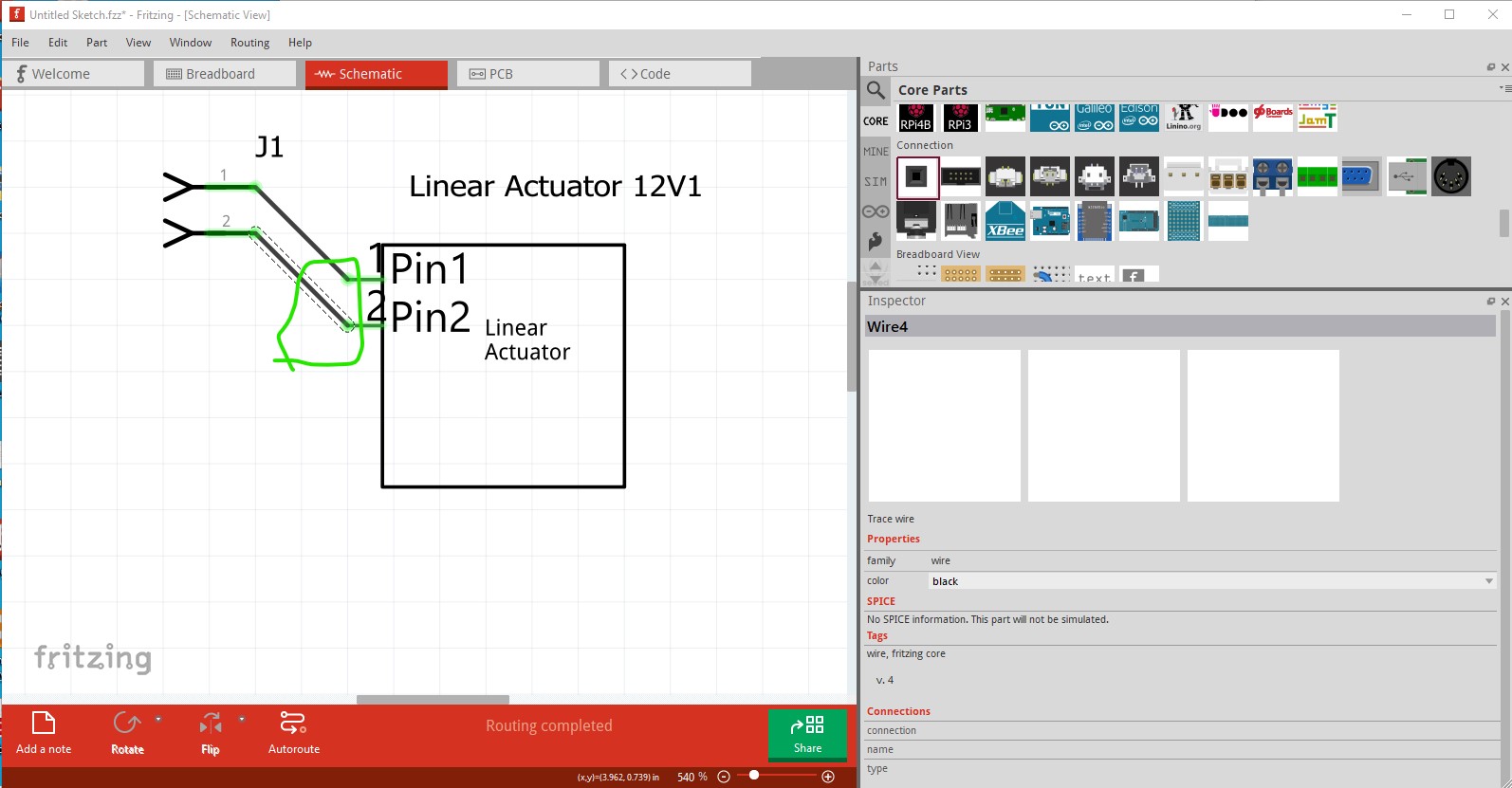
which came from this .fzpz file
linear-actuator_12v_aldrin-inbaraj_1.fzpz (3.6 KB)
Peter