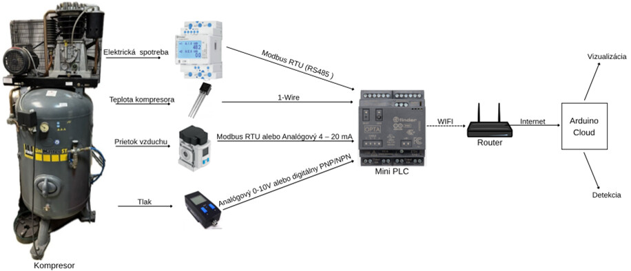
For my bachelor’s thesis, I need to create an electrical diagram for connecting these devices that collect data about compressed air products. here are the links to their websites / datasheets and the communication diagram between the devices and Arduino OPTA WiFi:https://docs.rs-online.com/2310/A700000007788744.pdf
Pressure sensor SDE1-D10-G2-R14-C-P1-M8 Festo Pressure Sensor SDE1-D10-G2-R14-C-P1-M8 Festo - Axxa - Motor Control & Automation
Flow sensor SFAM-62-1000L-M-2SV-M12 sorry can not add link because i am new user
Good evening,
you surely have to do that in the block diagram, not in the graphical view of the components, right?
Best, Harald!
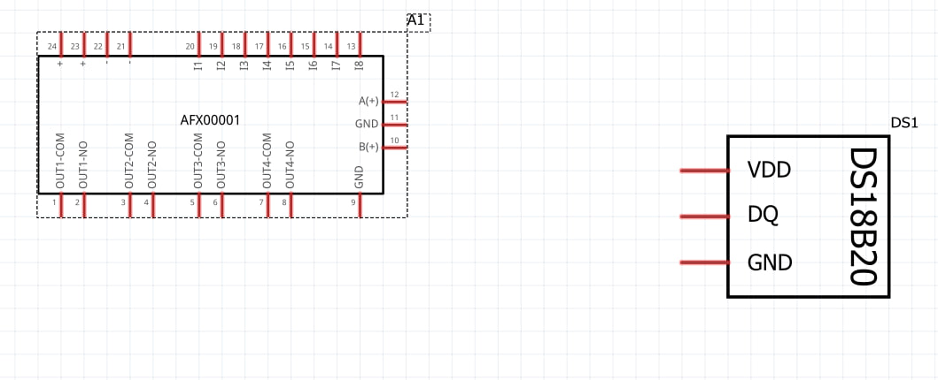
I need to do this in the program fritzing in the schematic section. I already found the mini PLC Arduino OPTA, DS18D20
For the schematic area, there’s a plugin for Inkscape. You can use it to create very good block diagrams.
Hi all!
I have been working on an extension for Inkscape to create rectangular schematic symbol .svg files for use in Fritzing. I think I created a useful tool to speed up creation of schematic symbols, and now I want to share it with the community.
It’s available on github:
https://github.com/revolt-randy/Fritzing-Schematic-an-Inkscape-Extension.
To install:
In Inkscape, the edit menu → user preferences → system will have an option for ‘User extensions’ - allowing you to open the folder to…
If you’d like, I can also help you out.
For that, I’ll need the exact names of the components and the exact names of the connections.
I would then use the schematic view in the breadboard view and PCB view as well. The two components would then only be useful for you.
Regards, Harald!
1 Like