@celestinoG The gerber files are plain text. Any or all of them could be modified manually, or with some other tool. I am not current with what the exact contents of each or the files looks like. A quick scan shows (only) a few things that look like labels. As long as you follow the rules for the specific file, and do not change anything that is referenced by one of the other files, there should be no problems.
I got the gerber export to work  Though the steps to get there are not trivial, and I do not know what it would take to get Inkscape, or another SVG editor to do what I found to be needed. Or at least what worked, though since I did multiple things, not all of them may have been actually required to get it to work. Mostly, I was editing the svg file with a text editor. It is just an xml text file, that I can read (and modify) directly. At least when changing one element at a time.
To start, I ungrouped the elements in Inkscape a couple of times, to get rid of the transform wrappers. That also deleted the board and silkscreen layers, so I recreated those. The plain svg result of that, I feed through the FritzingCheckPart tool, which (among other tweaks) converted the style attributes that Inkscape used to individual formatting attributes. That still did not work. Next I moved the silkscreen layer/group to before the board layer. Not enough yet. Not working after manual removal of (more) unneeded meta data and attributes from the svg.
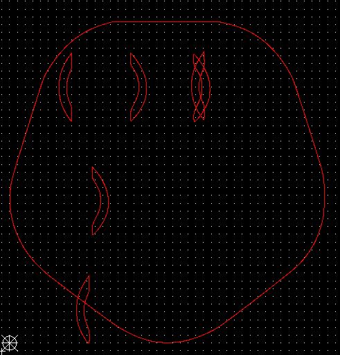
Finally I looked closely at the board path element that defines the shape and cutouts. I noticed a pattern to what was being shown by the gerber viewer, and the way the cutouts were defined. An svg path element (which is what the board is) can have either and both absolute coordinates and relative coordinates. Each cutout is created by a closed block of elements (a shape) following a move (“m” or “M”) command. All of the cutouts after an absolute move (M) showed up in the gerber view. Cutouts that were started with a relative move (m) worked correctly ONLY IF the preceding cutout used an absolute move. Some of the rest (m following another m) were on the gerber view, but in the wrong locations. I have not (yet) confirmed this, but I strongly suspect that what is happening, is that every relative move cutout is being positioned offset from whereever the previous absolute move was specified, instead of continuing from where the immediately preceding relative move left off. Many of the relative move commands had exactly the same offset. That resulted in them being in exactly the same location on the gerber. I also suspect that gerber acts like svg in this regard. A cutout on top of a cutout cancels the first cutout. So (especially) the rectangular cutouts only showed up at all when there were an odd number of them after an absolute move.
@vanepp. I strongly suspect a bug in the gerber export code for (at least) the custom board file. A work around is to never use more than one “m” command in a path after an absolute “M”. Other relative coordinates seem to work fine. All of the elements in a cutout block (after an m or M command) used (and still use) relative coordinates. With no problems seen. I need to create a simpler test case to verify assumptions from the symptoms seen. This indicates that a single cutout should work fine. More than that only work if absolute coordinates happen to be used, or the preceding cutout used absolute coordinates. 2 relative moves in a row fails, or puts the cutout in the wrong spot.
While manipulating the svg file, I encountered another gerber export bug we saw before. An svg close (z) command draws a straight line from the current active point to the latest move reference point. However, the gerber export is not inserting that final line segment, leaving an open shape instead of a cutout. Last time this was seen, I think it was just silkscreen, not cutout. Likely a general problem with the way the gerber export code handles (does not handle) a z command in a path.
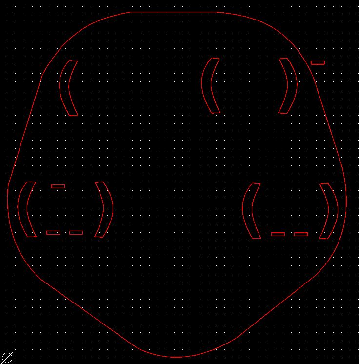
Here is the svg file used to create a test gerber export, which looks like the image in the pdf below. I included the gerber file too. Both gerber and pdf renamed to append .fzz to the name, to keep the forum software happy. Download and rename to remove the .fzz to use them.

Untitled Sketch 5_contour.gm1.fzz (256.8 KB)
test gerber view.pdf.fzz (22.8 KB)
This should work, but I do not know how to describe the detailed steps needed to get there. I do now know how to tell any SVG editor to use absolute coordinates for move commands in a path. The manual fix was to collect the 6 cutouts (2 curved brackets and 4 rectangular dashes) needed to create one group, convert the move commands to absolute, adjusting the actual coordinates to match, then cloning the cleaned up block 4 times, and adjusting the absolute coordinates for the start of each individual cutout. In the process, the rectangular cutouts where changed to use straight line edges, instead of almost straight curve segments.
EDIT: bugs reported.
Gerber export missing and moving some custom pcb cutouts
gerber export does not include final segment of shape created by “z” command in svg path element
The missing and misplaced cutouts are a known problem, that has already been fixed in the development version.
The missing segment on cutout close still exists in the dev version.


 Though the steps to get there are not trivial, and I do not know what it would take to get Inkscape, or another SVG editor to do what I found to be needed. Or at least what worked, though since I did multiple things, not all of them may have been actually required to get it to work. Mostly, I was editing the svg file with a text editor. It is just an xml text file, that I can read (and modify) directly. At least when changing one element at a time.