I’m looking for an MSOP-10 component for my PLC controller — does something like that exist? How can I build one myself?
Thanks for the replies
I’m looking for an MSOP-10 component for my PLC controller — does something like that exist? How can I build one myself?
Thanks for the replies
Hi Hans Werner,
we can do that with Fritzing’s standard components. I’ll get back to you tomorrow — unless someone else has the part finished before then.
Cheers, Harald!
Thank you, and if you don’t mind, could you show me how you do that?
Then I could give it a try too
Have a lovely weekend
Thanks and regards
Hans Werner
Good morning,
I see two options. In the components under core, there is an IC that you can configure yourself. There you can set the label, number and labeling of the pins, as well as the pin spacing. Unfortunately, these ICs are THT, or I can’t find an SMD one.
You could now load an SMD PCB view via the component editor.
For example from the Timer 555 IC. If you go to the PCB view in the component editor, you can export it as an SVG.
However, you’ll then need to remove the watermark using Inkscape. Have you worked with Inkscape before?
Now I just need to open the new part in the component editor and load the PCB view I just saved with SMD in the PCB view.
The connectors still need to be checked in the component editor to make sure they are actually set to SMD. After that, I would also check a test version in the Gerber viewer or upload it to Aisler. There you can also see whether the SMD pads are interpreted correctly.
Of course, the pad spacing also needs to be verified against the datasheet.
I won’t be around for the first half of next week. Feel free to give it a try — you’ll surely find tutorials for Inkscape and the Fritzing component editor online as well.
When I’m back, we’ll take a look at your attempt and work on it further — or maybe it’ll already be done!
Making Fritzing parts yourself
Best, Harald!
Hey Harald,
So far so good… I have Linux, do you know if my Inkscape can do that too?
I downloaded it once…
Peter once made one like that for me but the gap was 0.10mm, the spacing of the IC is 0.5mm — couldn’t the IC be edited more easily?
Si5351A.fzpz (5.0 KB)
The only catch with the whole thing is that when trying to install it, Fritzing complained…
Hi Werner,
I also have LINUX.
sudo apt install inkscape
You don’t need to download it manually, that only causes problems with package dependencies, so it’s better to install the version from your distribution.
I’ll take a look at it on Thursday!
Best, Harald!
Or
sudo dnf install inkscape
for Fedora. Other variations depending on the package manager used for the specific linux distro.
have mint current version.
Hi Hans Werner,
have you tried working with Inkscape yet?
How far did you get and what problems did you run into?
Best, Harald!
Good evening Harald…
It is what it is, you plan something and it turns out differently than planned…
I have loads to do in the garden, up to my ears in it.
Including being forced into further training — Fritzing is on the back burner until mid-June for now… otherwise I’ll get an earful from Ecker…
I haven’t been able to test much yet from installing it and one attempt at starting it.
But an acquaintance mentioned that you could take KiCad models and adapt them? I had a look in KiCad and the component is there, so it would be doable… that’s the theory at least… unfortunately the program doesn’t convert KiCad parts into Fritzing, but everything else into KiCad… C’est la vie!!!
Hello Hans Werner,
Yes, that obviously takes priority. Just get in touch when you have time.
You can export the footprint from KiCad. But it still needs some reworking afterwards. You’d need Inkscape for that. In your case, I’d just grab a suitable footprint from Fritzing. Your chip is pretty much a standard part after all.
Best, Harald!
Hey Harald, a matching footprint from Fritzing or at least a suitable selection option for the blank ICs would be a real help.
I had hoped the new Fritzing would be better in that regard, but no such luck…
Plenty of new modules for Arduino and Co… but specific individual components get forgotten.
My Arduino #SDR Shield from ELKTOR — I had it mostly figured out at first, but then parts were missing for SMD. In the end I was just glad that my PCB guy could also work with PDF templates and made a board from them for me… What I learned from that: whatever you do, don’t try to solder 0603 components without the right soldering equipment…
Since then I know firsthand that tweezers can fly surprisingly well and stick into walls… but the shield works, I just still need a matching 3.5mm jack plug that actually fits the solder pad… I’ll get on it — tomatoes are on the agenda this weekend, after that I’ll have time!
I’ll check back in then.
Cheers,
Hans Wernert
Hello @Hans_Werner_Atzenhoe , my strategy is to look for parts that are official or still from Peter, in which case ideally a SOIC or similar.
An example here is the SOIC8 from the ATTiny13.
Open it in the part editor and then “Save as”.
Then in “My Parts” → “Export Part” e.g. as SOIC8.fzpz
You get:
SOIC8.fzpz (6 KB)
Rename this to SOIC8.zip, then open/extract it.
Of particular interest here is the PCB view, svg.pcb.prefix0000_a3f94c69ed232914d3b785e7552b9044_1_pcb.svg
![]()
You can then open this with the editor of your choice.
The interesting part is:
    <g gorn="0.0" id="copper1" >
        <rect connectorname="1" fill="#F7BD13" gorn="0.0.0" height="2.2098" id="connector0pad" stroke="none" stroke-linecap="round" stroke-width="0" width="0.6096" x="0.2284"  y="5.2324"/>
        <rect connectorname="2" fill="#F7BD13" gorn="0.0.1" height="2.2098" id="connector1pad" stroke="none" stroke-linecap="round" stroke-width="0" width="0.6096" x="1.4984"  y="5.2324"/>
        <rect connectorname="3" fill="#F7BD13" gorn="0.0.2" height="2.2098" id="connector2pad" stroke="none" stroke-linecap="round" stroke-width="0" width="0.6096" x="2.7684"  y="5.2324"/>
        <rect connectorname="4" fill="#F7BD13" gorn="0.0.3" height="2.2098" id="connector3pad" stroke="none" stroke-linecap="round" stroke-width="0" width="0.6096" x="4.0384"  y="5.2324"/>
        <rect connectorname="5" fill="#F7BD13" gorn="0.0.4" height="2.2098" id="connector4pad" stroke="none" stroke-linecap="round" stroke-width="0" width="0.6096" x="4.0384"  y="0"/>
        <rect connectorname="6" fill="#F7BD13" gorn="0.0.5" height="2.2098" id="connector5pad" stroke="none" stroke-linecap="round" stroke-width="0" width="0.6096" x="2.7684"  y="0"/>
        <rect connectorname="7" fill="#F7BD13" gorn="0.0.6" height="2.2098" id="connector6pad" stroke="none" stroke-linecap="round" stroke-width="0" width="0.6096" x="1.4984"  y="0"/>
        <rect connectorname="8" fill="#F7BD13" gorn="0.0.7" height="2.2098" id="connector7pad" stroke="none" stroke-linecap="round" stroke-width="0" width="0.6096" x="0.2284"  y="0"/>
        <g gorn="0.0.8" id="copper0" />
    </g>
Those are your 8 pads.
Notable is [stroke=“none” stroke-linecap=“round” stroke-width=“0”], meaning there is no stroke, and the stroke that isn’t there has round ends and a thickness of 0. This can be reduced to stroke=“none”.
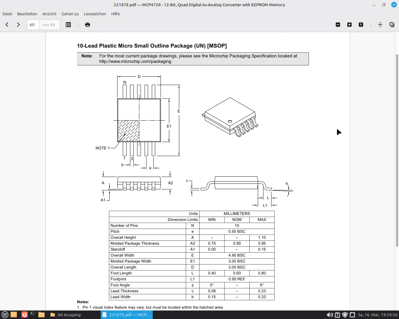
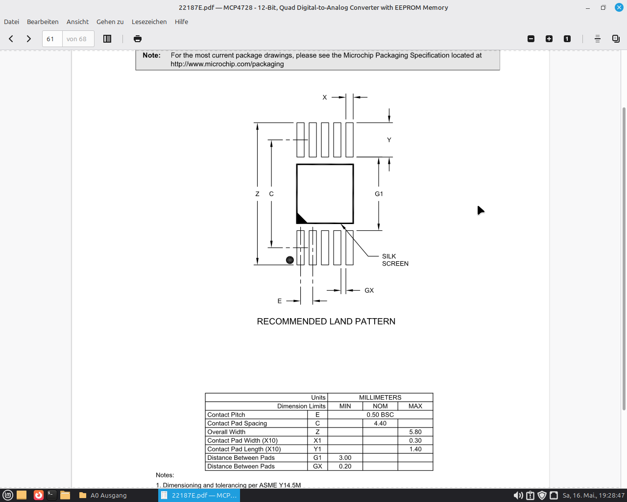
We also know that the pad width is 0.3mm and the spacing is 0.5mm.
These become
<g gorn="0.0" id="copper1">
    <!-- Bottom Row: Pins 1 to 5 (Left to Right) -->
    <rect connectorname="1" fill="#F7BD13" gorn="0.0.0" height="1.4000" id="connector0pad" stroke="none" width="0.3000" x="0.2000" y="4.4000"/>
    <rect connectorname="2" fill="#F7BD13" gorn="0.0.1" height="1.4000" id="connector1pad" stroke="none" width="0.3000" x="0.7000" y="4.4000"/>
    <rect connectorname="3" fill="#F7BD13" gorn="0.0.2" height="1.4000" id="connector2pad" stroke="none" width="0.3000" x="1.2000" y="4.4000"/>
    <rect connectorname="4" fill="#F7BD13" gorn="0.0.3" height="1.4000" id="connector3pad" stroke="none" width="0.3000" x="1.7000" y="4.4000"/>
    <rect connectorname="5" fill="#F7BD13" gorn="0.0.4" height="1.4000" id="connector4pad" stroke="none" width="0.3000" x="2.2000" y="4.4000"/>
    <!-- Top Row: Pins 6 to 10 (Right to Left) -->
    <rect connectorname="6" fill="#F7BD13" gorn="0.0.5" height="1.4000" id="connector5pad" stroke="none" width="0.3000" x="2.2000" y="0.0000"/>
    <rect connectorname="7" fill="#F7BD13" gorn="0.0.6" height="1.4000" id="connector6pad" stroke="none" width="0.3000" x="1.7000" y="0.0000"/>
    <rect connectorname="8" fill="#F7BD13" gorn="0.0.7" height="1.4000" id="connector7pad" stroke="none" width="0.3000" x="1.2000" y="0.0000"/>
    <rect connectorname="9" fill="#F7BD13" gorn="0.0.8" height="1.4000" id="connector8pad" stroke="none" width="0.3000" x="0.7000" y="0.0000"/>
    <rect connectorname="10" fill="#F7BD13" gorn="0.0.9" height="1.4000" id="connector9pad" stroke="none" width="0.3000" x="0.2000" y="0.0000"/>
    <g gorn="0.0.10" id="copper0" />
</g>
Now we need to adjust the silkscreen and the dimensions, the end result then looks like this:
<?xml version='1.0' encoding='UTF-8' standalone='no'?>
<!-- Created with Fritzing (http://www.fritzing.org/) -->
<svg xmlns="http://www.w3.org/2000/svg" baseProfile="tiny" height="0.228346in" version="1.2" viewBox="0 0 2.6738 5.8" width="0.105268in" x="0in"  y="0in">
    <desc>
        <referenceFile>sparkfun-analogic_soic8_pcb.svg</referenceFile>
    </desc>
    <g gorn="0.0" id="copper1">
        <!-- Bottom Row: Pins 1 to 5 (Left to Right) -->
        <rect connectorname="1" fill="#F7BD13" gorn="0.0.0" height="1.4" id="connector0pad" stroke="none" width="0.3" x="0.25" y="4.4"/>
        <rect connectorname="2" fill="#F7BD13" gorn="0.0.1" height="1.4" id="connector1pad" stroke="none" width="0.3" x="0.75" y="4.4"/>
        <rect connectorname="3" fill="#F7BD13" gorn="0.0.2" height="1.4" id="connector2pad" stroke="none" width="0.3" x="1.25" y="4.4"/>
        <rect connectorname="4" fill="#F7BD13" gorn="0.0.3" height="1.4" id="connector3pad" stroke="none" width="0.3" x="1.75" y="4.4"/>
        <rect connectorname="5" fill="#F7BD13" gorn="0.0.4" height="1.4" id="connector4pad" stroke="none" width="0.3" x="2.25" y="4.4"/>
        <!-- Top Row: Pins 6 to 10 (Right to Left) -->
        <rect connectorname="6" fill="#F7BD13" gorn="0.0.5" height="1.4" id="connector5pad" stroke="none" width="0.3" x="2.25" y="0"/>
        <rect connectorname="7" fill="#F7BD13" gorn="0.0.6" height="1.4" id="connector6pad" stroke="none" width="0.3" x="1.75" y="0"/>
        <rect connectorname="8" fill="#F7BD13" gorn="0.0.7" height="1.4" id="connector7pad" stroke="none" width="0.3" x="1.25" y="0"/>
        <rect connectorname="9" fill="#F7BD13" gorn="0.0.8" height="1.4" id="connector8pad" stroke="none" width="0.3" x="0.75" y="0"/>
        <rect connectorname="10" fill="#F7BD13" gorn="0.0.9" height="1.4" id="connector9pad" stroke="none" width="0.3" x="0.25" y="0"/>
        <g gorn="0.0.10" id="copper0" />
    </g>
    <g gorn="0.1" id="silkscreen">
    <!-- Left Body Edge Outline -->
        <line class="other" stroke="#f0f0f0" stroke-linecap="round" stroke-width="0.1524" x1="0.1262" x2="0.1262" y1="1.4" y2="4.4"/>
    <!-- Right Body Edge Outline -->
        <line class="other" stroke="#f0f0f0" stroke-linecap="round" stroke-width="0.1524" x1="2.6738" x2="2.6738" y1="1.4" y2="4.4"/>
    <!-- Pin 1 Dot Indicator (Positioned near Pad 1 at bottom-left) -->
        <circle class="other" cx="0.125" cy="5.6000" fill="none" r="0.05" stroke="#f0f0f0" stroke-width="0.15" />
    </g>
</svg>
and visually (400% zoom):
![]()
If anyone still needs a matching 10-pin SVG:
<?xml version='1.0' encoding='UTF-8' standalone='no'?>
<!-- Created with Fritzing (http://www.fritzing.org/) -->
<svg xmlns="http://www.w3.org/2000/svg" baseProfile="tiny" height="0.61in" version="1.2" viewBox="0 0 33.2669 15.494" width="1.30972in" x="0in" y="0in">
    <desc>
        <referenceFile>msop10_schematic.svg</referenceFile>
    </desc>
    <g gorn="0.0" id="schematic">
        <!-- Main Interior Component Box (10 pins) -->
        <rect class="interior rect" fill="#ffffff" height="15.24" stroke="none" width="22.86" x="5.20347" y="0.127"/>
        <text class="text" fill="#000000" font-family="'Droid Sans'" font-size="1.49931" gorn="0.0.1" id="label" stroke="none" stroke-width="0" text-anchor="middle" x="16.6335" y="7.21735">MSOP-10</text>
        <!-- Border Lines -->
        <line class="other" stroke="#000000" stroke-linecap="round" stroke-width="0.3175" x1="5.20347" x2="28.0635" y1="0.127" y2="0.127"/>
        <line class="other" stroke="#000000" stroke-linecap="round" stroke-width="0.3175" x1="28.0635" x2="28.0635" y1="0.127" y2="15.367"/>
        <line class="other" stroke="#000000" stroke-linecap="round" stroke-width="0.3175" x1="28.0635" x2="5.20347" y1="15.367" y2="15.367"/>
        <line class="other" stroke="#000000" stroke-linecap="round" stroke-width="0.3175" x1="5.20347" x2="5.20347" y1="15.367" y2="0.127"/>
        <!-- LEFT SIDE PINS (1 to 5) -->
        <!-- Pin 1: -->
        <line class="pin" connectorname="PIN1" gorn="0.0.34" id="connector0pin" stroke="#787878" stroke-linecap="round" stroke-width="0.246944" x1="0.123472" x2="5.20347" y1="2.667" y2="2.667"/>
        <rect class="terminal" fill="none" gorn="0.0.35" height="0.0001" id="connector0terminal" stroke="none" width="0.0001" x="0.123472" y="2.667"/>
        <text class="text" fill="#8c8c8c" font-family="'Droid Sans'" font-size="0.881944" stroke="none" text-anchor="middle" x="2.66347" y="2.29658">1</text>
        <text class="text" fill="#787878" font-family="'Droid Sans'" font-size="1.23472" stroke="none" text-anchor="start" x="5.9443" y="2.91394">Pin1</text>
        <!-- Pin 2: -->
        <line class="pin" connectorname="PIN2" gorn="0.0.30" id="connector4pin" stroke="#787878" stroke-linecap="round" stroke-width="0.246944" x1="0.123472" x2="5.20347" y1="5.207" y2="5.207"/>
        <rect class="terminal" fill="none" gorn="0.0.31" height="0.0001" id="connector4terminal" stroke="none" width="0.0001" x="0.123472" y="5.207"/>
        <text class="text" fill="#8c8c8c" font-family="'Droid Sans'" font-size="0.881944" stroke="none" text-anchor="middle" x="2.66347" y="4.83658">2</text>
        <text class="text" fill="#787878" font-family="'Droid Sans'" font-size="1.23472" stroke="none" text-anchor="start" x="5.9443" y="5.45394">Pin2</text>
        <!-- Pin 3: -->
        <line class="pin" connectorname="PIN3" gorn="0.0.26" id="connector3pin" stroke="#787878" stroke-linecap="round" stroke-width="0.246944" x1="0.123472" x2="5.20347" y1="7.747" y2="7.747"/>
        <rect class="terminal" fill="none" gorn="0.0.27" height="0.0001" id="connector3terminal" stroke="none" width="0.0001" x="0.123472" y="7.747"/>
        <text class="text" fill="#8c8c8c" font-family="'Droid Sans'" font-size="0.881944" stroke="none" text-anchor="middle" x="2.66347" y="7.37658">3</text>
        <text class="text" fill="#787878" font-family="'Droid Sans'" font-size="1.23472" stroke="none" text-anchor="start" x="5.9443" y="7.99394">Pin3</text>
        <!-- Pin 4: -->
        <line class="pin" connectorname="PIN4" gorn="0.0.22" id="connector6pin" stroke="#787878" stroke-linecap="round" stroke-width="0.246944" x1="0.123472" x2="5.20347" y1="10.287" y2="10.287"/>
        <rect class="terminal" fill="none" gorn="0.0.23" height="0.0001" id="connector6terminal" stroke="none" width="0.0001" x="0.123472" y="10.287"/>
        <text class="text" fill="#8c8c8c" font-family="'Droid Sans'" font-size="0.881944" stroke="none" text-anchor="middle" x="2.66347" y="9.91658">4</text>
        <text class="text" fill="#787878" font-family="'Droid Sans'" font-size="1.23472" stroke="none" text-anchor="start" x="5.9443" y="10.5339">Pin4</text>
        <!-- [NEW] Pin 5: -->
        <line class="pin" connectorname="PIN5" id="connector8pin" stroke="#787878" stroke-linecap="round" stroke-width="0.246944" x1="0.123472" x2="5.20347" y1="12.827" y2="12.827"/>
        <rect class="terminal" fill="none" height="0.0001" id="connector8terminal" stroke="none" width="0.0001" x="0.123472" y="12.827"/>
        <text class="text" fill="#8c8c8c" font-family="'Droid Sans'" font-size="0.881944" stroke="none" text-anchor="middle" x="2.66347" y="12.4566">5</text>
        <text class="text" fill="#787878" font-family="'Droid Sans'" font-size="1.23472" stroke="none" text-anchor="start" x="5.9443" y="13.0739">Pin5</text>
        <!-- RIGHT SIDE PINS (6 to 10) -->
        <!-- Pin 10: -->
        <line class="pin" connectorname="PIN10" gorn="0.0.6" id="connector2pin" stroke="#787878" stroke-linecap="round" stroke-width="0.246944" x1="33.1435" x2="28.0635" y1="2.667" y2="2.667"/>
        <rect class="terminal" fill="none" gorn="0.0.7" height="0.0001" id="connector2terminal" stroke="none" width="0.0001" x="33.1435" y="2.667"/>
        <text class="text" fill="#8c8c8c" font-family="'Droid Sans'" font-size="0.881944" stroke="none" text-anchor="middle" x="30.6035" y="2.29658">10</text>
        <text class="text" fill="#787878" font-family="'Droid Sans'" font-size="1.23472" stroke="none" text-anchor="end" x="27.3226" y="2.91394">Pin10</text>
        <!-- Pin 9: -->
        <line class="pin" connectorname="PIN9" gorn="0.0.14" id="connector7pin" stroke="#787878" stroke-linecap="round" stroke-width="0.246944" x1="33.1435" x2="28.0635" y1="5.207" y2="5.207"/>
        <rect class="terminal" fill="none" gorn="0.0.15" height="0.0001" id="connector7terminal" stroke="none" width="0.0001" x="33.1435" y="5.207"/>
        <text class="text" fill="#8c8c8c" font-family="'Droid Sans'" font-size="0.881944" stroke="none" text-anchor="middle" x="30.6035" y="4.83658">9</text>
        <text class="text" fill="#787878" font-family="'Droid Sans'" font-size="1.23472" stroke="none" text-anchor="end" x="27.3226" y="5.45394">Pin9</text>
        <!-- Pin 8: -->
        <line class="pin" connectorname="PIN8" gorn="0.0.10" id="connector5pin" stroke="#787878" stroke-linecap="round" stroke-width="0.246944" x1="33.1435" x2="28.0635" y1="7.747" y2="7.747"/>
        <rect class="terminal" fill="none" gorn="0.0.11" height="0.0001" id="connector5terminal" stroke="none" width="0.0001" x="33.1435" y="7.747"/>
        <text class="text" fill="#8c8c8c" font-family="'Droid Sans'" font-size="0.881944" stroke="none" text-anchor="middle" x="30.6035" y="7.37658">8</text>
        <text class="text" fill="#787878" font-family="'Droid Sans'" font-size="1.23472" stroke="none" text-anchor="end" x="27.3226" y="7.99394">Pin8</text>
        <!-- Pin 7: -->
        <line class="pin" connectorname="PIN7" gorn="0.0.18" id="connector1pin" stroke="#787878" stroke-linecap="round" stroke-width="0.246944" x1="33.1435" x2="28.0635" y1="10.287" y2="10.287"/>
        <rect class="terminal" fill="none" gorn="0.0.19" height="0.0001" id="connector1terminal" stroke="none" width="0.0001" x="33.1435" y="10.287"/>
        <text class="text" fill="#8c8c8c" font-family="'Droid Sans'" font-size="0.881944" stroke="none" text-anchor="middle" x="30.6035" y="9.91658">7</text>
        <text class="text" fill="#787878" font-family="'Droid Sans'" font-size="1.23472" stroke="none" text-anchor="end" x="27.3226" y="10.5339">Pin7</text>
        <!-- Pin 6: -->
        <line class="pin" connectorname="PIN6" id="connector9pin" stroke="#787878" stroke-linecap="round" stroke-width="0.246944" x1="33.1435" x2="28.0635" y1="12.827" y2="12.827"/>
        <rect class="terminal" fill="none" height="0.0001" id="connector9terminal" stroke="none" width="0.0001" x="33.1435" y="12.827"/>
        <text class="text" fill="#8c8c8c" font-family="'Droid Sans'" font-size="0.881944" stroke="none" text-anchor="middle" x="30.6035" y="12.4566">6</text>
        <text class="text" fill="#787878" font-family="'Droid Sans'" font-size="1.23472" stroke="none" text-anchor="end" x="27.3226" y="13.0739">Pin6</text>
    </g>
</svg>
200%:

Moin Echter Knaller, that’s quite simple… if the solder pads aren’t properly degreased and you start soldering anyway, something like that happens pretty quickly.
And on the topic of crawling around = 0815 I think? ![]()
There’s a simple solution… in garden supplies there are leaf collection sheets for transporting leaves — put that under your chair and table, it has high sides all around, so everything that falls from above lands in this fabric sheet… simple!!!
I’m done for now, in the truest sense of the word… I had a circulatory collapse.
One should eat a little more in the morning than just overnight oats (oats with cinnamon) and drink plenty of fluids… I’m feeling better now… it was just way too hot today… apparently it’s supposed to get considerably cooler again…
So, about my problem
The tarp option isn’t going to work. Our lab isn’t used just by me — a tarp is neither acceptable from an electrostatic nor a safety standpoint.
Also, I spend most of my time moving around with magnifying lenses in front of my eyes, so trip hazards are guaranteed to succeed.
First of all, get well soon and take care of yourself — heat is nothing to mess around with, especially when you’re well past 18. That’s not a problem I have; at work and at home it’s barely 20 degrees right now.
Oh?!
Sorry, didn’t know that, I was thinking more along the lines of hobby mechanics,
so you’re cruising around like Puk the house fly? ![]()
well, I was like that too, but since I couldn’t be bothered anymore and kept sitting on the damn thing, I just gave it up…
how does it work in terms of Fritzing and that part?
I only have the text… convert it into a file with Linux? and open Fritzing and paste it` I don’t think that works, it’s just a footprint, maybe like adding a new board shape?
You have several options. You can paste the text in an editor and save the whole thing as “filename.svg”, or you can right-click on the image under “and visually (400% zoom)” and then click “Save as”. The effect is the same.
I only did the text thing to show what the files look like.
You should do the same with the image for the schematic.
I can put together a finished part for you if you have a bit more information — at minimum I’d need to know which chip it is. Ideally also post an image with the pin layout, so I don’t have to go looking for it.
Alternatively, you can also open and edit your fzpz file
you then just need to insert the saved PCB image in the PCB view.
Hey there Echter Knaller,
The part in question is the IC MCP4728, which I need for my PLC.
You can use it to run 4 boards via I2C, each with 4 outputs = 16 analog outputs in total.
Since the Arduino only has analog inputs for measuring, you can use this to control devices.