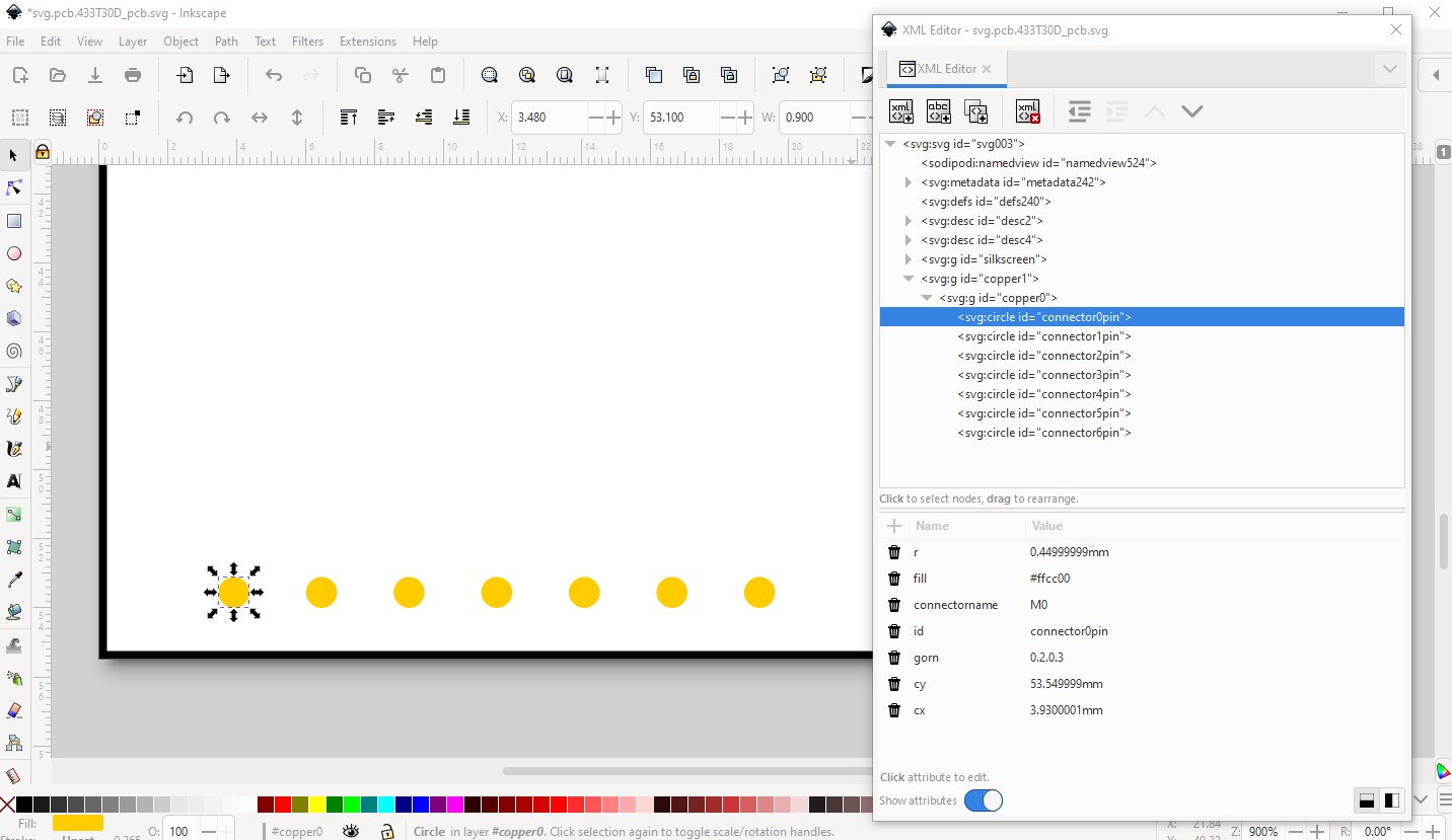
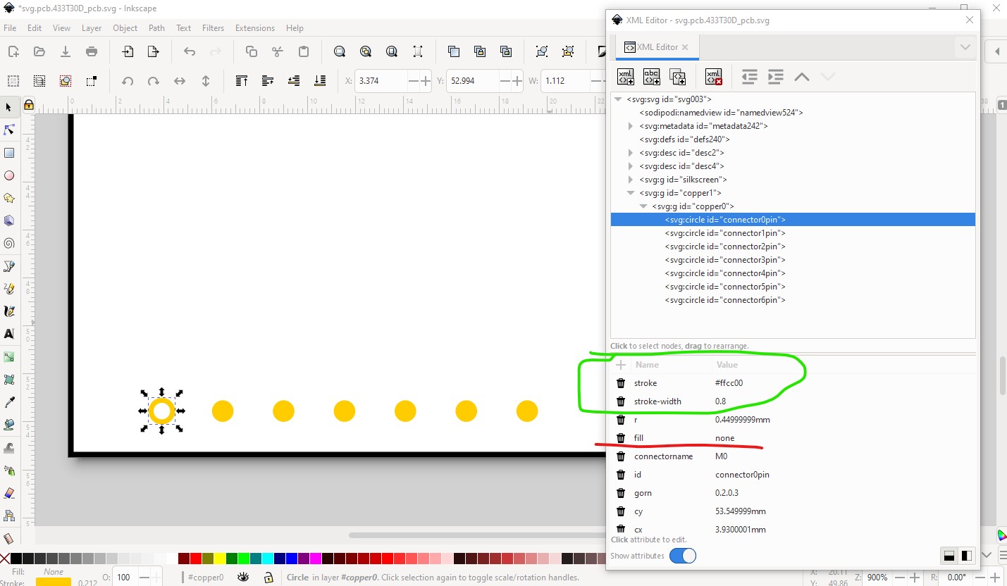
which is a pad which will not generate a hole in the gerber file, it needs to add a stroke and stroke-width attribute and the fill attribute set to none like this:
Your pcb svg is the incorrect scale (how to rescale it is in the tutorial along with how to set the hole size assuming you are using Inkscape as your svg editor) so the hole size will likely be incorrect here. At the correct scale (1 drawing unit = 1/1000in) the stroke-width should be 20 to set a 20 thou pad around the hole. In this case the hole size should be 0.038in to be correct to take a 0.1in header (and as noted the hole generated by this change is probably not correct!)