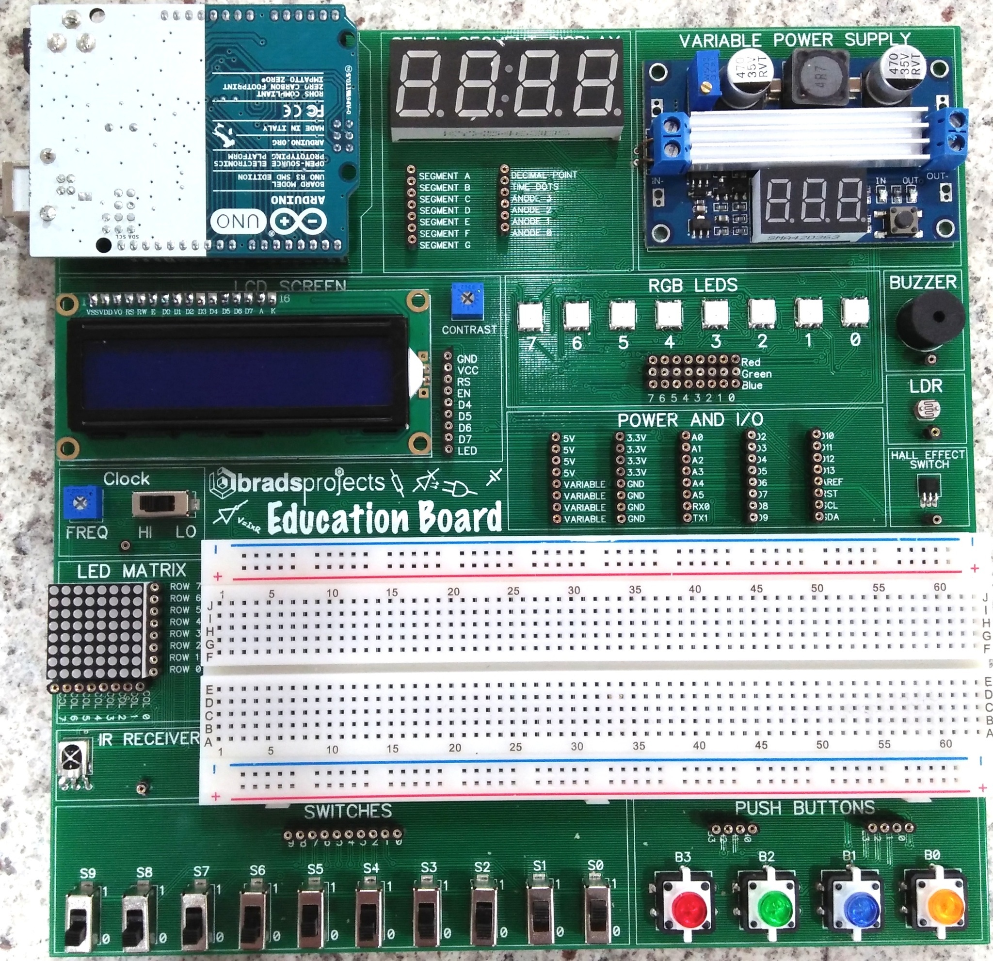
Hi everyone, I am an electronics teacher and have developed an ‘education board’ for use in my classes. It is a 200mm x 200mm circuit board which contains:
An Arduino Uno
4-Digit seven segment display
DC-DC Boost converter (allows you to boost the 5V USB voltage anywhere up to 40V)
16x2 LCD display
8 RGB LED’s
Piezo buzzer
LDR
Hall Effect Sensor
Variable Clock (astable multivibrator)
8x8 LED Matrix
830 tie point breadboard
Infrared Receiver
10 Digital Toggle Switches
4 Push Buttons with LED’s
I have already been using fritzing to show students how to connect their circuits, now I’d like to be able to show them on my education board.
Is there anyone who could create this form me - we can work out a part creation cost etc…
It looks to me as if your first problem is going to be the breadboard. The Fritzing breadboard appears to be a compiled in part (i.e. I can’t see how to export it as a fzpz file as parts editor is greyed out, usually indicating a compiled in part). At 900 plus pins (and lots of busses) recreating that will be a major pain unless someone knows how to get it as a part.
In Inspector there are only a couple of options, so there must be a fixed BB svg of it somewhere.
In header you pick the pin count and you can save it as a new part and it will assemble it and export a part of that number of pins, but the BB isn’t pin selectable so it must just be single svgs.
I found it, its in the core parts directory as breadboard2.fzp (with the associated svgs). I’m just working on a modified version of it to see that it works then I’ll poke a bit further from there. Luckily they used odd pin names such as pin1A so there shouldn’t be conflicts with other parts. Connectors has an odd parameter ‘connectors ignoreTerminalPoints=“true”’ which I haven’t seen before, hopefully that won’t interfere with the normal operation of other connectors of a non breadboard nature but I guess I’ll see .
Currently it is using breadboard view for both schematic and pcb (presumably it blanks them out in both views). I’m assuming (hoping?) that it will let me slide a standard schematic view in without complaining, I don’t expect he needs PCB view only breadboard and schematic.
Sorry for replying late here guys. It looks as though this was more of a hard task than I thought. I realised it was a big job to begin with - do you think it would be alright to leave the breadboard out of my PCB and then have the standard breadboard within fritzing to appear over the top of my PCB?
I had thought about that… the only problem is that the breadboard will always be on the bottom in the Breadboard View, it cannot be placed above the PCB part. I suppose you could leave a cutout in the PCB for the breadboard.
If Van has the breadboard svg it’s no trouble to paste it on to another svg. It would also have the pins in the svg so it would be pretty much complete already.
I was thinking about the SCH view and the 900 pins, and it would probably have to be the 128 5 pin headers and 4 50 pin headers that are laid out so that you have room to add components.
You wouldn’t need the breadboard in the schematic view… it would be used just like a standard breadboard that has no schematic view. It would be best to start with the breadboard .fzp then add all the other pins. Only the added pins would need to be in schematic view. Also it would be nice to create the sch.view with sub parts (LED, Power Supply, RGB LEDS, LED Screen, Power and I/O, LED Matrix, Stitches, and Push Buttons) as a sub part. Take the breadboard image, Uno, LEDs, Power Supply, etc. images and past them all on the breadboard .svg. I think the only part that you would need to draw up is the power supply. The rest are in Fz. Hide the PCB image which is very simple to do…
That should keep you busy for at least a week or two…
Indeed I found the component files for breadboard in the core parts directory and created an fzpz of it which loads the breadboard fine so the isn’t a problem. Now I’m learning to cut and paste in Inkscape to get the rest of the parts in to the breadboard base (and have discovered that when cutting an pasting Inkscape does indeed add subscripts such as breadboard-1 at least when cutting and pasting!) so I agree (assuming I can figure out the grouping) this should work out. If Brad gets a better offer I’d take it other wise I’ll have a bash at it as a learning exersize although it may take me a while.
Thanks very much again for taking the time to have a look at this guys.
@vanepp, I have no better offer at this stage, so if you’re willing then i’d love for you to look at creating it. I of course would not expect you to do it for nothing so I am happy to pay you in one form or another - whether it be a monetary amount, or perhaps I could send you one of these learning boards when they are made, along with other projects I have made:
OK, but it may take me some time my first pass at adding the lcd and a 9 pin connector to the breadboard part has run in to an issue where the 9 pin connector pins don’t work in breadboard (but do work in schematic). Using cut and paste in Inkscape to include multiple parts in one isn’t something I’ve done before and it looks like it may be a bit exciting . When I removed the cut and paste 9 pin connector from the group that cut and paste put it in, the scale changed from .9 inches to 100 inches so there are obviously things about cut and paste I don’t understand. Even correcting that (and changing things in the fpz file) haven’t yet managed to get breadboard working properly but I expect I’ll figure it out (or give up and ask for help here ).
Fixed that problem they used breadboardbreadboard (rather than breadboard) for the layer ID fixing that looks to have fixed my breadboard connector problem. A question: I assume switches b0 to b3 are led push buttons? With 4 of the connectors the button contact and the other 4 the led
(in which case, which connector bank is switches and which is led?) I think everything else is pretty much self evident.
Great to see you back with your new project. Hope you remember me as I’ve helped you with Toaster board. Actually, what got me here is the usual email notifications from fritzing summary email as well as the old post which you bumped a few days back. Sorry, I was supposed to get back to you a few months back but unfortunately, I was stuck on a couple of big projects. I was working on Altium projects and they were quite big and some take longer than expected and multiple revisions. I remember saying you that I’ll help you with your website too and I’ll do it ASAP. I’m slowly getting away from busy days and will very soon contact you on your email.
BTW, belated XMAS and Newyear wishes. All the best with your project and hope it gets huge success.
I think this is doable. I just finished the graphics for the breadboard view (only the connectors for the lcd and breadboard currently work as the rest aren’t set yet and the text needs to be added later) but it at least this gives you an idea of what it will look like in breadboard.
A question on the io pins. The photo (which is what I’m going from) is unclear around the digital i/o pins on the 4th and 5th connectors. I’m assuming they are the digital pins from the Arduino, but it isn’t clear what the last 4 are
connector86 d10(?)
connector87 d11(?)
connector88 d12(?)
connector89 d13(?)
connector90 (?) (can’t read the lettering on these …)
connector91 (?)
connector92 (?)
connector93 (?)
As well as I’m asking, are the screw terminals on the variable power supply intended to be usable (i.e do they need connectors in Fritzing?)
I see the variable power comes out on the female pins in the power section. (edit:)
One more question: the 4 led push buttons I’m assuming the left most 4 connectors are the switches and the right most 4 the leds (red, green, blue and orange) is that correct? What is the lettering on the connectors as well (it is unreadable in the photo) the buttons appear to be 83 82 81 and 80


 Great to see you back with your new project. Hope you remember me as I’ve helped you with Toaster board. Actually, what got me here is the usual email notifications from fritzing summary email as well as the old post which you bumped a few days back. Sorry, I was supposed to get back to you a few months back but unfortunately, I was stuck on a couple of big projects. I was working on Altium projects and they were quite big and some take longer than expected and multiple revisions. I remember saying you that I’ll help you with your website too and I’ll do it ASAP. I’m slowly getting away from busy days and will very soon contact you on your email.