Just downloaded your work and it looks fantastic, well done and I can’t express enough my appreciation for your work. It’s just fantastic, even just playing around with the LCD connections and the breadboard is great, I can see how easy things are going to be showing students in class how to wire up their circuits.
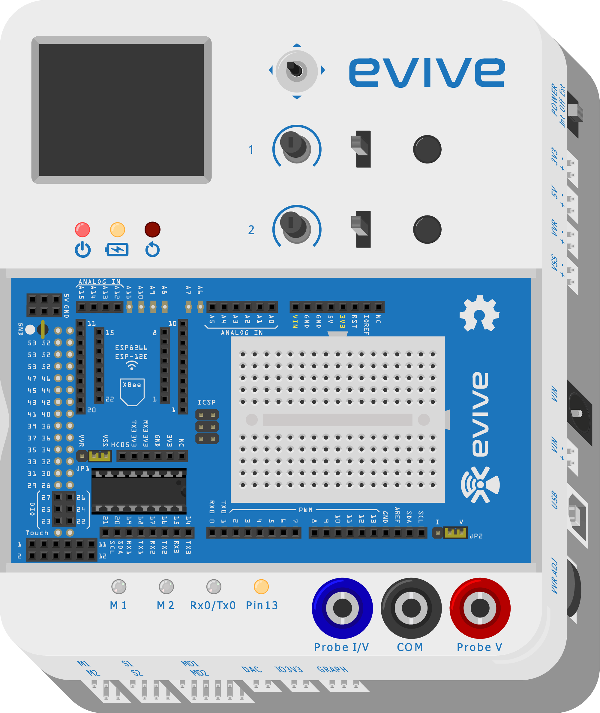
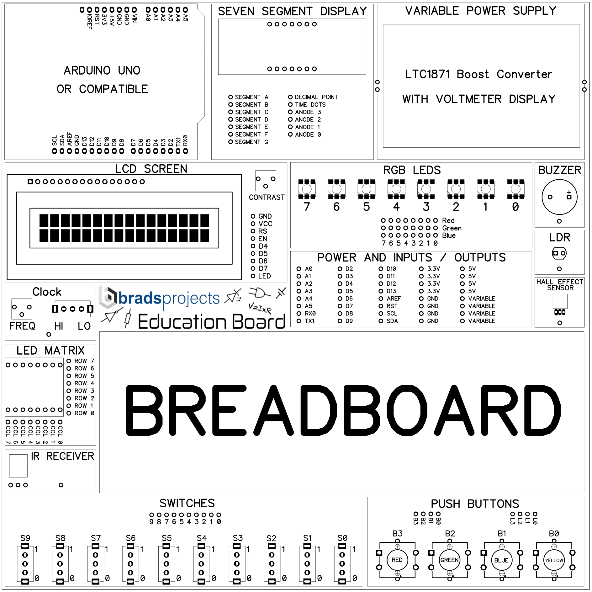
I have slightly modified the layout of the power and input / output pins (this is so you can use shorter wires due to most of the I/O pins being basically in the centre now) - I have attached a screenshot of how they have been re-arranged. Also, the screw connectors on the variable power supply are not used. They are a permanent fixture of the design with the left two connections being the 5V input from the USB port and the right two connections being the boosted variable output. these two connections then go to the four GND connections and the four VARIABLE connections which I think you were referring to above. Hopefully the screenshot clarifies this. The buttons are labelled B3, B2, B1 and B0 and then for the LED’s in the buttons, they are labelled - L3, L2, L1 and L0.
Also I thought I should mention, the Arduino Uno is upside down in the image because it plugs in to the Education Board. however these pins aren’t accessible at the Arduino, but down at the POWER AND INPUTS / OUTPUTS section.
Hi @Dee_Faux, I know how you feel, i’ve been busy with a number of electronic projects lately also There is no rush on the website and appreciate your offer of help on the site - in fact, I’ve been running through an online web developer course which has been benefical, since normally I just make a website using wordpress or drupal or something similar and rely on everyone else’s themes and plugins - so it has been a good learning experience Merry Christmas and a happy new year to you also!
Thanks for the reply. Like the word “No Rush” . Yes, that is a good start and sure you’ll enjoy the learning experience. In fact, I wasn’t ready to hard code the website from the ground up which is way too far from my skill set. I thought of doing it in either drupal or WP as I recently did mine in drupal. The learning curve is quite steep in drupal but if you are cable of learning then you can do great sites compared to WP. Anyway, If you need my hand then do let me know and I’ll jump in. I’ll get back to you sometime very soon when I get past the busy days. Tnx
Nah the jpeg above is fine. I already know most of the pins and that drawing clears up the few I didn’t know. Now all I’ve got to do is edit in proper pin numbers in to the breadboard and merge the rest of the schematic bits in (and decide if I want to tackle movable schematic parts or as I probably will, do a simple schematic to start and tackle movable elements in version 2 ).
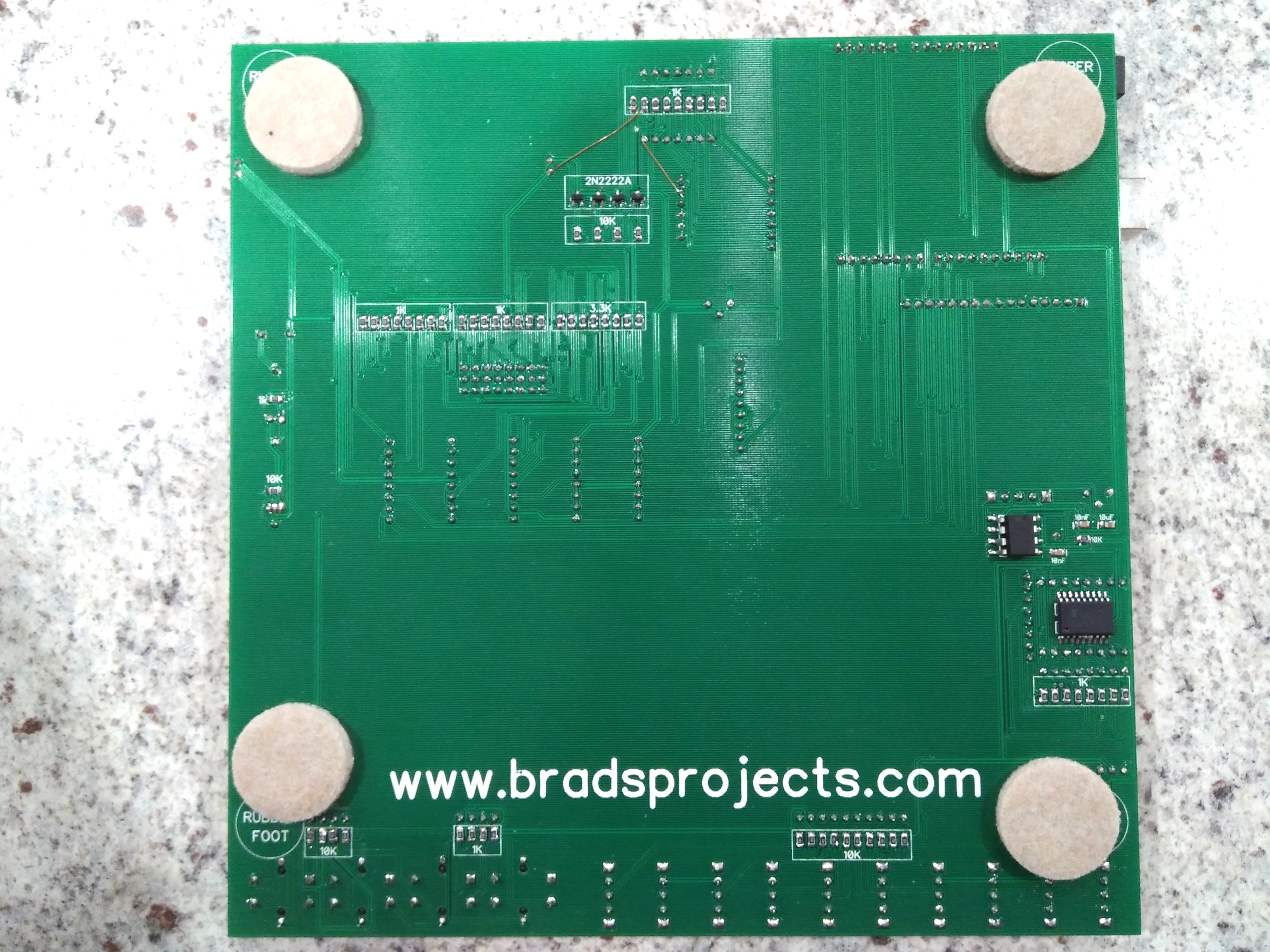
Some electrical (not Fritzing related ) thoughts on this, which if the boards are done may be too late. I don’t see current limiting resistors on the various led leads. While values may be difficult (because you likely want to support multiplexing) experience tells me (because I do it when prototyping ) that the kids are likely to accidentally connect 5V to the led pins which will likely burn the led out without a current limiting resistor in the way on the board (which may be there, and just not obvious in the photo). Sockets for the leds so they can be replaced when this happens would be one solution.
Good point @vanepp, I put all of the ‘driving’ circuitry on the underside of the PCB such as the 555 timer, current limiting and pull down resistors, transistors for the seven segment display and darlington array for the LED matrix. They are all surface mount components and by having them under the board, it makes the top less confusing.
Are the rgb leds common cathode or common anode? Since the one in Fritz is common cathode I’ll assume that for the moment and change it if necessary. Same for the leds in the pushbuttons common cathode or common anode (this only matters in schematic)
One more question: On the Arduino outputs there is A4 and A5 and a separate SCL (which should also be A4?) and SDA(which should also be A5?). I’m assuming the pins are bussed together internally (as with the power wires) or am I missing something?
Thats right, the current version of the Arduino Uno has the seperate SCL and SDA pins as well as the A4 and A5 pins so I thought i’d also have these connections as well even though they are in fact connected together. I.E. A4 = SDA and A5 = SCL.
I’m almost done Schematic got finished yesterday and the fpz file for connectors is done, but I just ran in to an issue with connector terminals in schematic that are miss placed and won’t move (probably why they are miss placed ) so I need to fix that (probably by replacing the polygon with a rectangle) and then I should be ready to upload an update.
Really appreciated all the hard work you’ve been putting into this and certainly look forward to seeing your completed part however there is no rush, I’m just thankful someone has been able to figure it out!
Its good there is no rush, because I just tried a test version and Frtizing is unhappy about most connections (or possibly just a few) and there looks to be a font issue betwen Inkscape and Fritzing as the fonts are misplaced in Fritzing (likely to be translate problems I think) so I’m somewhat further than I hoped from a review copy (but I’m having fun and learning!)
You can change the text to paths, and that gets around all the mucking around text/font problems. No one is ever going to change the text in the future so it’s not going to be a problem.
If it was a common part, ie TO-220, where you might have to mod it to another part, yes it’s better with the text/font. But because this will never have to be changed, it would probably be better with the trace to path.
 There is no rush on the website and appreciate your offer of help on the site - in fact, I’ve been running through an online web developer course which has been benefical, since normally I just make a website using wordpress or drupal or something similar and rely on everyone else’s themes and plugins - so it has been a good learning experience
  . Yes, that is a good start and sure you’ll enjoy the learning experience. In fact, I wasn’t ready to hard code the website from the ground up which is way too far from my skill set. I thought of doing it in either drupal or WP as I recently did mine in drupal. The learning curve is quite steep in drupal but if you are cable of learning then you can do great sites compared to WP. Anyway, If you need my hand then do let me know and I’ll jump in. I’ll get back to you sometime very soon when I get past the busy days. Tnx