TL/DR: Does anyone know of a LM317K in the TO-3 package?
Full backstory:
I have a power supply that I built in the 90’s, which uses a LM317k (TO-3 package). My wiring and soldering skills back then were poor (still are), which resulted in a rats nest of a finished project.
So I’m rewiring this PSU, and have modeled it in Fritzing. This has been a life saver for me. When messing around with the PCB feature, I started getting excited about having a PCB created and turning this into a proper PSU.
But when hacking this together in Fritzing, I was forced to use a LM2575 in TO-220 package, because I could not find the LM317k. I am about to use a MJ11016 in place of the LM317K, because the one I found for Fritzing is in the TO-3 package.
I am still very new to Fritzing. Should I just modify the MJ11016 and make it look like a LM317K? If I do that, is it good form to give credit to @vanepp, who I think made the MJ11016 that I found?
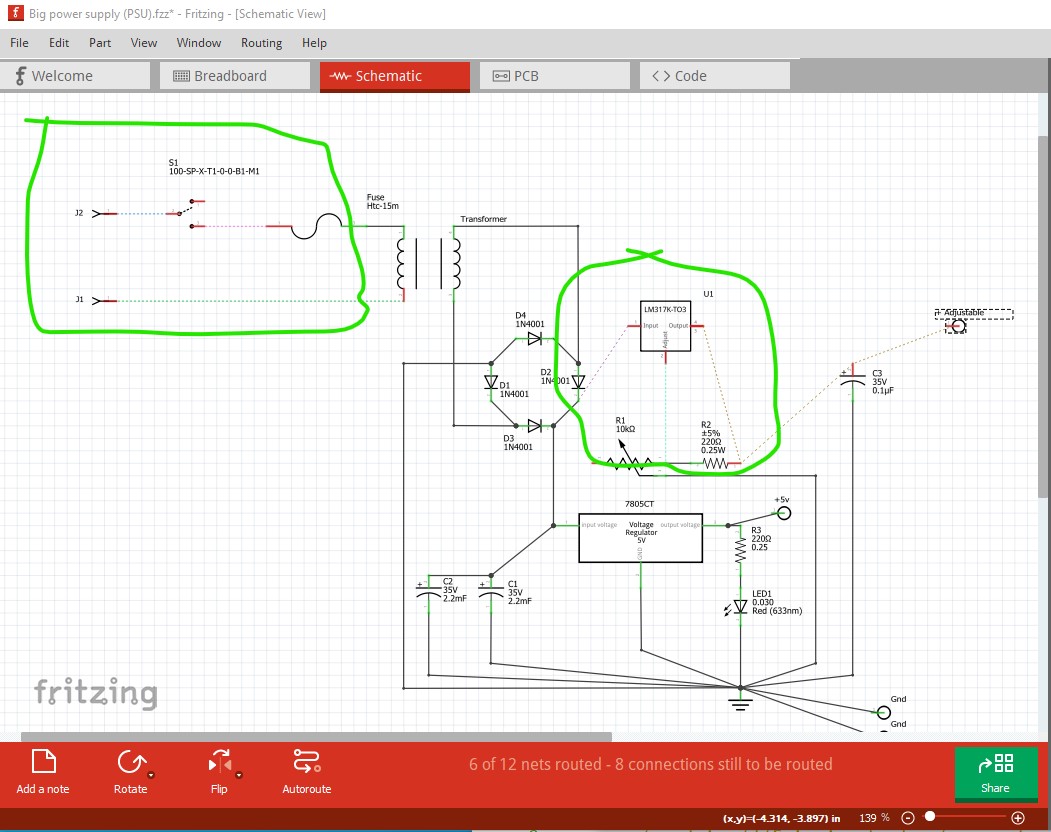
OK, a number of problems here. Starting with breadboard I made a new custom part for the LM317 mostly to change schematic to match a voltage regulator rather than a darlington transistor (your modified part seems to work fine!) That is circled in blue in the image below. Then I replaced the switch (which wasn’t showing up in schematic for some reason!) with another one that does appear in schematic that is circled in green in the image. Then I added two 1 pin headers to produce pads in pcb that the power cord can connect to. I don’t expect you will use actual headers, they are just to get a connection and a pad in pcb. With that done breadboard looks fine.
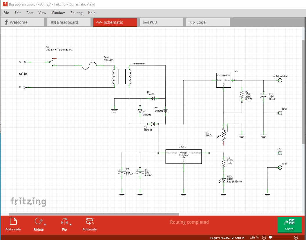
Now we need to do some clean up to make schematic look neater, ending up with this. I moved parts around and used ground indicators (which all connect to each other) to reduce the visual clutter of the ground lines. Note we now have an AC input and a switch in schematic.
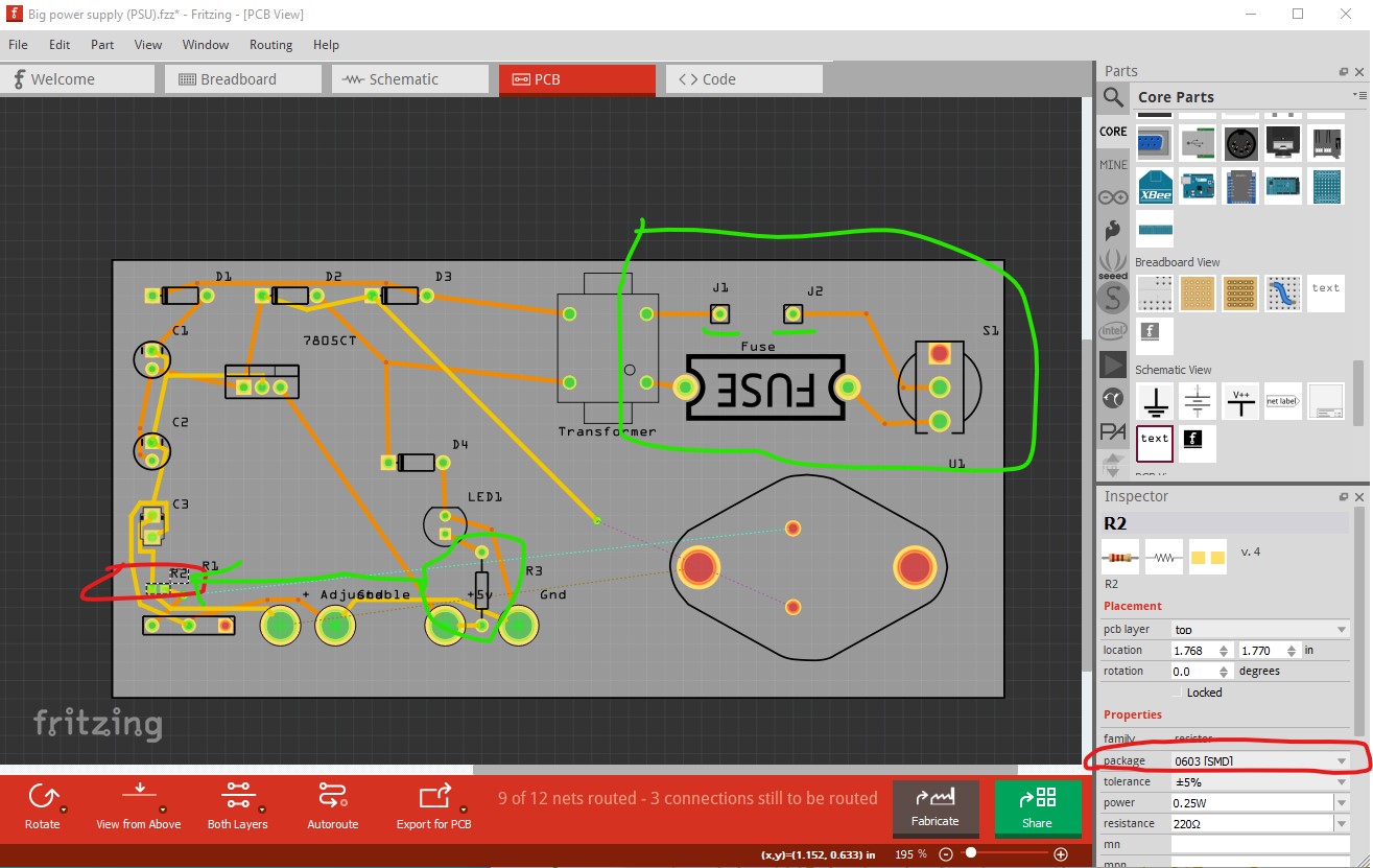
On to pcb which has a number of problems. R2 is set to be a 603 SMD resistor which I expect is not what you want. A standard through hole resistor like R3 is more likely what you want. C3 is also SMD.
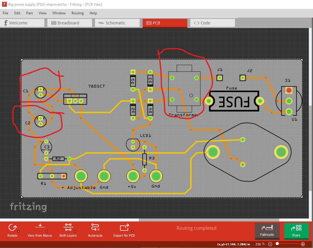
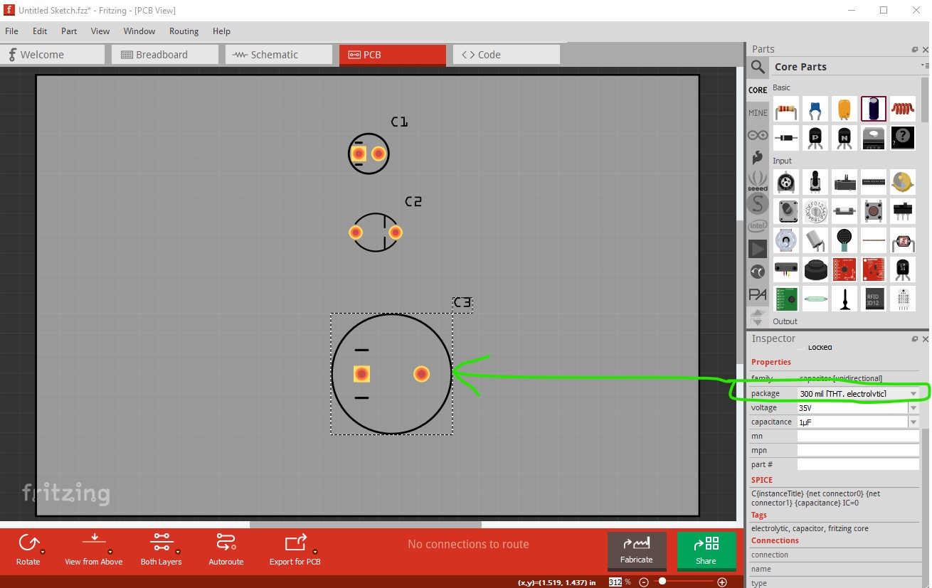
Here I changed all the SMD components to THT via inspector. However if you intend to mount the transformer on the pcb (as opposed to via wires in to the pads on the board) you need to verify the holes match the footprint which they likely don’t. You may need a custom part for the transformer.
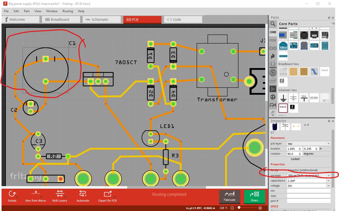
It seems likely to me that C1 is a couple of thousand microfarads and thus is larger than 0.1in spacing. You can also adjust that in inspector to match the real capacitor like this:
You also may need to put heatsinks on the 7805 and LM317 if you are supplying much current. They are both linear regulators and will get hot at high current. Hope this helps!
Breadboard:
After posting that file, I removed and replaced the switch, and it works much better now.
The pin headers is a good idea for the AC input.
Schematic:
Not sure why I didn’t think of adding more ground points.
PCB:
You are correct about the SMD devices. The transformer is the only thing which is not a through-hole device. Also, it’s freaking huge. I hold it to the PCB with two 1/4-20 bolts.
Parts which are not mounted to the PCB:
Potentiometer
Switch
Fuse
Banana plugs (both sets)
LED
Voltmeter
Other:
One thing I failed to bring up is that I’m not using 4 diodes to build my own full-wave rectifier, but am using a ECG5312 (seen here).
I also failed to add the voltmeter, but it’s not essential to the schematic. In this photo you can see:
the capacitors are large, like you predicted
the voltage regulators have heat sinks, like you recommended
the transformer is hefty
Two questions:
How do I correlate the capacitor package in Fritzing to the ones I used?
Will you share the custom LM317K you made? I don’t know how to make the changes you did.
A google search for “fritzing part bridge rectifier” (since I remember fixing one up ) turns up:
and there may be more I think, perhaps one more suited to what you need. Again if you have a data sheet for the one you have I can make a new part for it.
Best bet is to measure the spacing between the leads. If it is a multiple of 0.1in (and less than 0.3in) you can change the package in inspector to get a bigger cap. If they are larger than that then you would need a custom part made for them and we would need the data sheet or measurements of the cap to make one (assuming you want to mount it on the pcb!)
Yes. I meant to include my .fzz file (which has my new part in the temp parts bin where you can export it by right clicking on it and selecting export file.) Here is my .fzz