I am designing a circuit to control two 5V lamps using an ESP32. My end goal is to make it a “production” PCB to learn the full workflow of designing circuits.
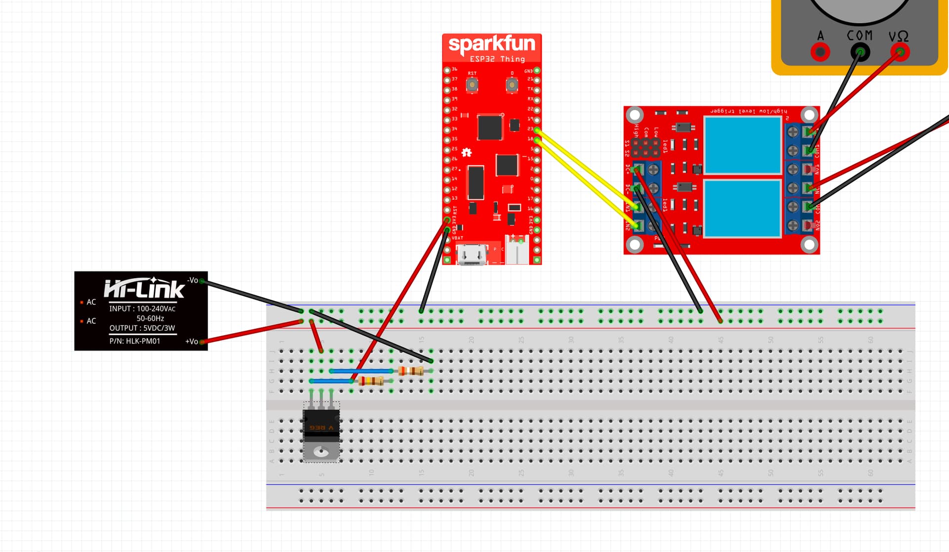
For now, I have started with the basics by laying out some parts in the breadboard view of Fritzing:
5V Power Supply
Voltage regulator
ESP32 dev kit
2 channels relay modules
2 multimeters (in place of lamps because I could not find any generic power draw in Fritzing)
Some notes:
I know that the ESP32 dev kit supports 5V but I would like eventually to remove it so I prepared the work to power it with 3.3V with the voltage regulator; but I am highly unsure of what I have done
The GPIO pins were chosen at random
The PSU says “3W” but I am looking to get the 10W instead (5V 2A)
I would love to get feedback on the current design, flaws, improvements, etc.
Thank you!
Edit: I kept looking into voltage regulator and I think it might make more sense to replace the generic, adjustable, LM317 I had chosen with a fixed LD1117V33 for 3.3V? Although I understand that requires to add capacitors?
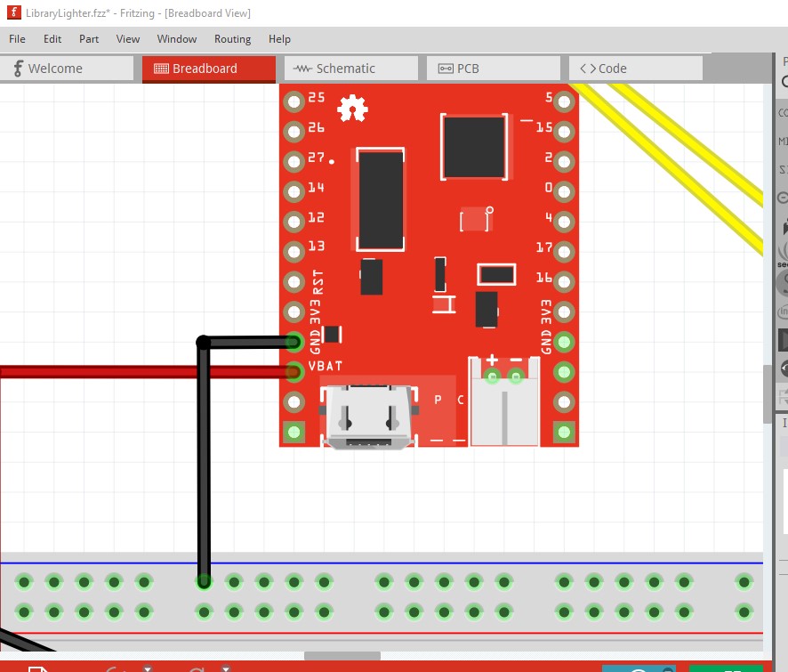
It looks mostly fine. Connecting to the 3.3V pin however is problematic. It isn’t intended (although it may work) that this run off 3.3V. There is an internal voltage regulator for 3.3V which as long as VBAT is disconnected and the USB cable is not connected may work (in theory the voltage regulator will be shut off and may or may not object to 3.3V being applied to it!) Reading the Sparkfun docs would probably be wise. This would be the correct way to provide 5V to the circuit (and I expect the only approved connection, that or USB.)
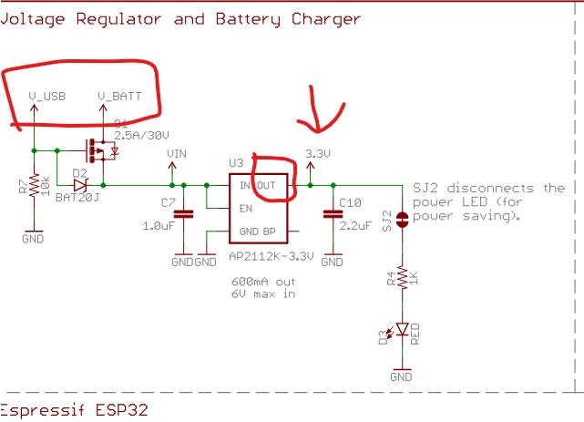
from the schematic on the Sparkfun site the circuit looks like this.
It is expected that either Vbat or the USB 5V will power the board via the voltage regulator on board. If neither Vbat or USB is powered the voltage regulator should be off and may (or may not) tolerate 3.3V being supplied to its output pin. I doubt that connection is recommended though. As to the fritzing part light bulb issue of bulbs, there are none in core parts but a google search of the form “fritzing part light bulb” turns up a number of bulbs (both low voltage and power line) on the net and one of them may do what you want. As well you need to find out if the relay module will run on 3.3V or if it wants 5V to power it! It may not run on 3.3V, the Songle relays in those boards are usually 5V (and sometimes 12V) and may not work on 3.3V.
Point noted for the 3.3V connection to the dev board. I assume my “production” PCB will then look a little different than this prototype since I intend to only have an ESP32 without a dev board in the PCB, and that runs off 3.3V. Any thoughts on the voltage regulator part? And on LM317 vs LD1117V33 (or even AP2112K that is used in the Sparkfun ESP32 Thing devboard according to the screenshot you’ve posted)?
Also very good point on if the relay module accepts 3.3V signal. I will make sure to double check that. An additional questions on relay modules: my two light bulbs draw little current (400mA for one and 200mA for the other ones). I wonder if it’s possible to get rid of the relays either entirely or with something else? I find relays quite bulky.
For efficiency use one of the buck regulator modules. A linear regulator is around %30 or less efficient (getting less efficient with higher voltage input) a buck regulator is %80 to %90 efficient and doesn’t change much with input voltage. A google search for “frtizing part buck regulator” will find to ones that have Fritzing parts.
It is likely to accept ttl level inputs (i.e low < 0.7V, high >2.4V) and thus run on 3.3v logic. The relay in the board may be a 5V relay (they usually are) and that may not work in 3.3V.
For that amount of current a NPN transistor or a power MOSFET is probably a better bet. There are also SSR modules (even some with fritzing parts) an SSR being a solid state relay with typically a power MOSFET as the switching element.
For efficiency use one of the buck regulator modules. A linear regulator is around %30 or less efficient
Mmh, thanks! Do you have any suggestions in mind for a buck regulator? I liked the linear regulator because it’s is so tiny.
For that amount of current a NPN transistor or a power MOSFET is probably a better bet. There are also SSR modules (even some with fritzing parts) an SSR being a solid state relay with typically a power MOSFET as the switching element.