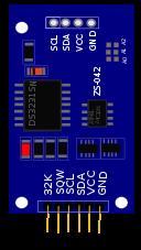
I am looking for the following DS3231 circuit as a fritzing part:
I have found this link but the part I can download is not the same as the image suggests.
So far I LOVE fritzing, looks like an amazing tool to use, but I think that creating a new part is an overly convoluted process, requires 3rd party applications, instead of just having a simple part editor. Is this true, or its just me not understanding what we have.
Well, after making more research I must say that the counterintuitive part editing is really a dealbreaker for Fritzing. While it is a lovely and nice looking application if there is no way to add parts in an easy manner (such as PCB123, or Eagle), then you are limited to use that handful of built in components.
It’s not that hard when you know how, it’s just that there is no comprehensive instruction for making parts.
You are always going to pay a price for the advanced graphics and the convenience of 3 circuit views automatically linked, but that’s what makes it a better system that beginners pickup a lot quicker.
If you are an Inkscape expert that drawing is a snap to make, and the rest is just manipulating nodes in Inkscape’s XML editor to the standard Fritzing likes, which doesn’t require any XML coding knowledge. Then you just do touchups in Fritzing Part Editor.
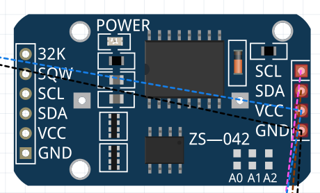
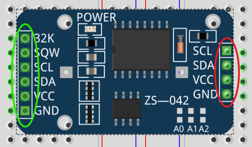
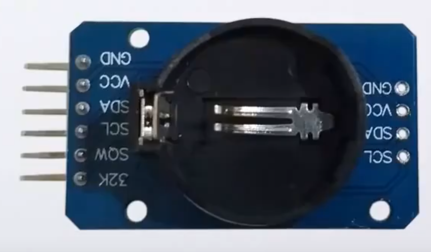
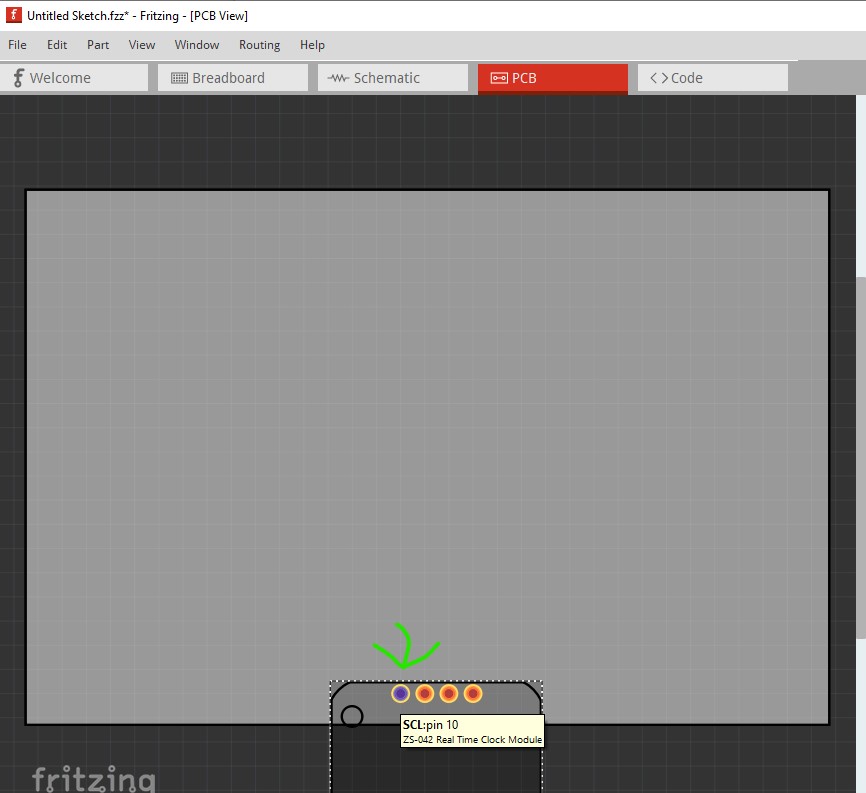
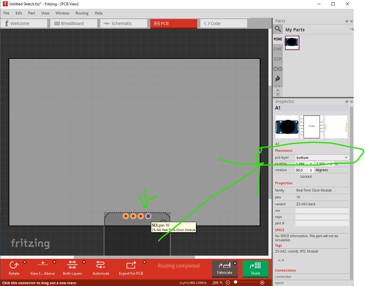
Hi, I’m using the DS3231 that you can find in Fritzing, see the attachment, I need to use the battery side but I noticed that is not possible to overturn it in the PCB section in Fritzing.
Do you have this part with battery side view or there’s a way to overturn it in the PCB view?
Did the datasheet state otherwise that it is not supposed to align?
Breadboard connectors should not be paths; they should be either rectangles/circles. So here is the corrected breadboard svg (but it does not have the fixed alignment issue)
Everything has to be grouped together and renamed as “breadboard”
In the schematic view, everything should be grouped together and the group has to be renamed to “schematic”
Following the IC pin numbering convention, I changed the schematic (by running @just_randy’s inkscape schematic extension. It is a life saver! Cut down my part creation time by 15 min).
The PCB view is missing a silkscreen that surrounds everything.
I removed the text as some users don’t want the text to be there. If you want silkscreen text you can just drag one out from the core bin.
I’m sorry but your part is wrong, the 4 pin strip is not overturn, you have GND-VCC-SDA-SCL that is correct for the chip side, for the battery side you should have SCL-SDA-VCC-GND pin order.
I’m talking about PCB view.
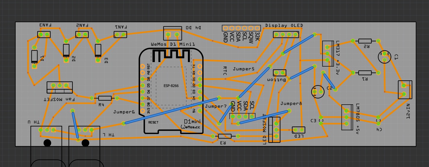
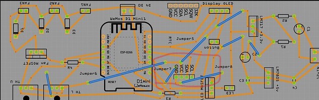
No my Friend, unfortunately is not possible to solve the problem in this way. I’m not using the breadboard view, I create the scheme and now I’m working on the PCB, I have specific requirements for placing the components on the PCB, take a look at my PCB, the RTC should be overturned so you can have the 4 pins in this order from left to right: SCL, SDA, VCC, GND.
If you turn it by 180° you need to place the component differently that it’s not my goal.
Then you need to provide sufficient information (starting by uploading your sketch, the .fzz file, upload is 7th icon from the left in the reply menu) and/or what view you are referring to. His part does not appear in this image as far as I can see but if it was there then moving which side of the board it was on would do what you want like this: standard view (top of the board)
Your part appears to be correct as is. The problem appears to be on his side of explaining what he is trying to do that is not working. Your part doesn’t appear to be in his sketch as far as I can see unless it is supposed to be the unlabeled red circle (which is impossible to tell without the sketch file!)
If that is the case then he needs to either mount the module on the bottom of the board or rotate the part 180 degrees (either of which are possible in Fritzing.) Mostly we need more clarity on what is wrong which is so far absent.
Sorry my friends, let me be more clear, the PCB picture I uploaded before is the PCB with the “old” chip side RTC component, obviously I change it with the new one, with the battery side on top, but the new one has the same pins order of the old one, so even if I share the picture of the PCB with the new part the result is the same.
If you overturn it (not turn by 180°), the pins should be in the reverse orders for the battery on top view compared to the chip side on top view.
Your trick to turn it by 180° is a workaround but isn’t correct if you want to place the component considering the same position on the PCB or breadboard.
At the end I used a generic 4 pins dupont connector so I can manage it as I need.

 Just in case you want it, I made a part for the DS3231 as a chip, without the breakout.