Ah!! I just realised I made a very fatal careless mistake!
Please use the fixed part:
ZS-042 Real Time Clock Module-backfixed.fzpz (10.5 KB)
Ah!! I just realised I made a very fatal careless mistake!
Please use the fixed part:
ZS-042 Real Time Clock Module-backfixed.fzpz (10.5 KB)
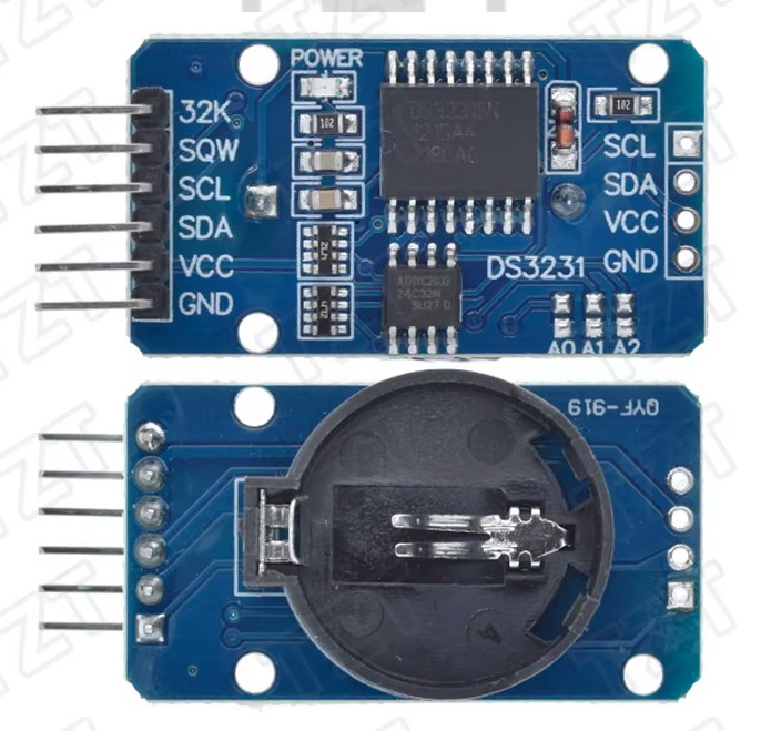
Your new part appears wrong to me. From the data sheet he posted
The original part appears correct. The top image above appears to be the board from the front. with the text of the connectors and the battery on the back of the board (and thus what the Fritzing part should look like which is your original part.) Your mew part has at least the mounting holes wrong and should have the RA header installed to be correct (which implies a change in pcb as the board will need to mount vertically.)
Peter
Can you help me create the fixed part please?
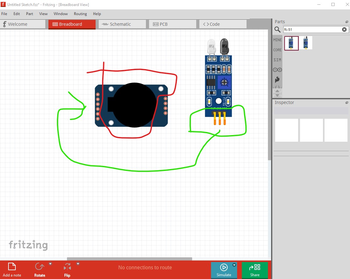
Your first part was correct. It showed the part from the top in breadboard as it should,and the mounting holes were correctly positioned. Pcb was also correct in both connections and layout. The OP still has not explained what he is complaining about or how he is intending to mount the board in pcb view. I don’t think the image he displayed (with the older part) will work, but there isn’t enough information to tell. Without sufficient explanation of what he wants to do, there isn’t much that can be done. It appears he wants to use the 4 end connectors (without the RA connector) which will presumably connect via wires with the module off board somewhere, but that is unclear. If that is the case there is no problem he can connect the wires however he wants. If he wants something different then he needs to explain it and we can explain his options.
Peter