Hi,
I am looking for the part DFR0165 (Gravity: IO Sensor Shield For Arduino Mega Due) in fritzing but it does not exist in fritzing. Could someone help me please ?
Thanks !
Cécile
From the svg file available on the DFR site it looks like @sgparry0407 has such a part (although only the breadboard svg is posted on the DFR site.) If he has such a part perhaps he will post it here (and now that email notifications are working again, he should see this reply via email because he hasn’t posted in quite a while.) If not a part could be made from the breadboard svg but it would be quite a bit of work as it is a complex part.
Peter
Thank you for your answer Peter.
Indeed, I have seen @sgparry0407’s SGV file. My problem is that I just learned how to make a part from a png file but this is extremely basic and this one looks pretty complicated to me 
Cécile
Your best bet is to hope Steve is reading email and responds, if not I’ll think about reconstructing the part from his breadboard svg. Even that will be a little complex, because it is a 90dpi Inkscape svg and the scale is slightly out ( the pins are not on .1 boundaries) when converted to 96dpi, as well as the lack of the needed fzp file and at least schematic (pcb may not be needed and/or I may be too lazy to do it.)
edit:
OK, I have poked at the breadboard svg a bit more and rescaled it properly (so the pads are on .1 boundaries), but it isn’t complete, and so may never have been finished. If Steve doesn’t reply within a few days I can make an fzp file with boiler plate pins (but no pin descriptions and no association with the svgs) and probably a schematic svg fairly easily. But I’m unlikely to do the typing for a couple of hundred pins in both svgs to associate the fzp pin description to the svgs. Assuming you can run Inkscape’s xml editor I can explain what needs doing and you can do the work (which is the tedious task of typing several hundred pin numbers in to xml editor in the svgs.) First thing to do though is make sure the svg on the DFR site matches the board you have, because if it doesn’t this won’t help. You may also want to look at this series as it describes what you will need to do:
https://forum.fritzing.org/t/part-creation-howto-part-1-breadboard-and-pcb/7692/2
Peter
Yes, I created the SVG; it was a long time ago and I cannot remember how far I got with the version I have - I think I got further than the one I donated to DFRobot but not much. Getting it dimensionally accurate from the various precursors was a nightmare, but I am confident I got that much right. I never completed the part because I decided I did not want to use it in the final project.
I will have a look at the SVGs I have and see how much further I got. I know I was trying to get a consistent pin naming to ease the creation of the fzp.
On a related note, I also got a long way with creating new Arduino Mega R3 parts (the current breadboard view for the mega is way off and lacking many useful connections), This included a novel new style of V shaped schematic symbol that allows suitably designed Uno and Mega shields to stack on the Arduino without a bazillion extra wire lines. I wish I had the time to finish it all!
Yep, that’s what I figured, if there was a full part it would have been posted. If you have a later version of the svg that would be appreciated and we will see what happens. As i said I’m willing to do the hard parts but likely not assign all the connectors to the svgs.
Peter
Thank you @sgparry0407 for your answer, I understand that looks like a tideous work !
Thanks @vanepp, I’m going to have a look at the link you posted.
Cécile
While tedious it isn’t all that hard. I have a script that will generate the connector boiler plate for the fzp file, so you will get a several hundred line list that looks like this:
  <connector id="connector0" type="male" name="">
    <description></description>
    <views>
      <breadboardView>
        <p svgId="connector0pin" layer="breadboard"/>
      </breadboardView>
      <schematicView>
        <p svgId="connector0pin" layer="schematic" terminalId="connector0terminal"/>
      </schematicView>
      <pcbView>
        <p svgId="connector0pin" layer="copper0"/>
        <p svgId="connector0pin" layer="copper1"/>
      </pcbView>
    </views>
  </connector>
  <connector id="connector1" type="male" name="">
    <description></description>
    <views>
      <breadboardView>
        <p svgId="connector1pin" layer="breadboard"/>
      </breadboardView>
      <schematicView>
in the fzp file (which you need to edit with a text editor.) The only thing that needs to change here is the
name="" field on each connector line and the
<description></description>
field under it to something like this:
   <connector id="connector0" type="male" name="pin 1">
    <description>AREF</description>
This causes Fritzing to display “pin1 AREF” when the mouse hovers over the pin in any view. The tedious part is that you need to edit all three (without pcb, only 2 in this case) svgs via Inkscape or another svg editor to associate the “connector0pin” and “connector0terminal”
fields with the appropriate element in the svg file like this (using Inkscape as the svg editor and the current breadboard svg):
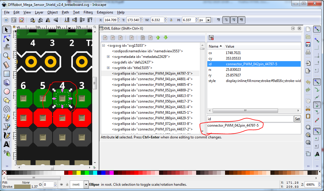
Here I have selected a random pin (the first one in the list) and displayed it with xml editor in Inkscape. What you need to do is change the id from connector_PWM_042pin_44797-5 to connector0pin to match the first entry in the fzp file connectors listing and then proceed in sequence for all the rest of the several hundred pins. Not at all difficult but time consuming. This can also be done graphically with the new parts editor (as long as the fzp file is already configured I think, as I don’t use the parts editor much), but I have rarely been able to make that work and find editing the files easier. Then you use xml editor to change connector_PWM_042pin_44797-5 to connector0pin like this:
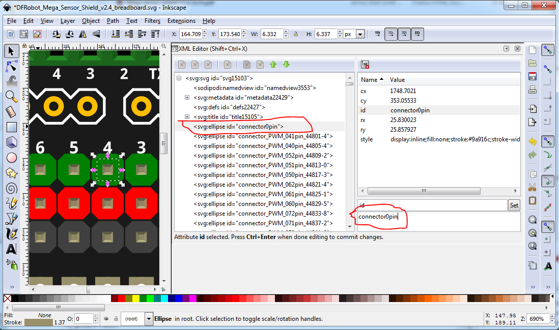
and repeat in both breadboard and schematic til all the pins are correctly associated (note that schematic has twice as many entries as it has both connector0pin and connector0terminal to set.) I am willing to help you out if you run in to problems (just post the svg and fzp file here), but not willing to put in the time for a board I don’t have. You may want to try this out by changing the first few connectors in the svg file on the DFR site and see how long it takes. Just replace the first couple of connector_PWM… entries with connector0pin, connector1pin etc. Then you need to decide if you want a part enough (and/or have sufficient time available) to do the work.
Edit
A useful tip to reduce typing: copy
connectorpin
in to the clipboard and then highlight the entire id data field in xml editor and replace it with connectorpin via a paste and type only the unique pin number between connector and pin in the above. Fir schematic I use
connectorterminal
and for pins, paste then highlight the terminal and replace it with 'pin-no’pin (where pin-no is a number such as 0.) Pin is less typing than terminal. As well if you make typing mistakes (which I usually do) FritzingCheckPart.py will catch and display them making them easy to correct in the svg.
Peter
Peter,
I have read your tutorial which helped me lot 
I will try this connector pin thing.
Cécile
OK, I’ll start fixing up a copy of schematic for this so it will be ready for you to add pins as well. Note the connections should start at connector0pin and go up in order. The labels in the current svg are not in Fritzing format but rather a description or what the pin connects to (which is valuable when assigning descriptions to the pins.) As I recall some of them are not defined yet so we may need to figure out what they do first. I usually pick one corner of the board (usually the left bottom) and make the first pin there connector0pin. You will also want to use this as the breadboard svg, it is the one from the DFR site but has been re scaled so the connectors are correctly on .1in boundaries:
DFRobot_Mega_Sensor_Shield_v2.4_breadboard.svg.fzp (827.5 KB)
Nope, didn’t correctly upload the svg. So the above is the svg file so you need to download it and remove the trailing .fzp from the file name and then edit the svg file with a text editor and change;
remove_me<?xml version="1.0" encoding="UTF-8" standalone="no"?>
to
<?xml version="1.0" encoding="UTF-8" standalone="no"?>
to convert it back to a valid svg file. Quirk of the new forum software, it used to be that just changing the extension was enough to fool it. It would probably be a good bet to change the first 8 or so connectors in the svg from the current format to connectorxpin and then post the svg (doing the same thing I did above) and I will check the format looks correct before you get too far along.
Peter
That’s great ! So nice of you !
I’ll add the pins
Thank you
Cécile
I expect the first item of business is to name the mega due pins on the svg (as they currently are not done.) I’d suggest a text file that associates
connector0 mega unused (maybe with the mega pin number of 251 from the Fritzing mega part, but that is optional)
connector1 mega IOREF
connector2 3V3
…
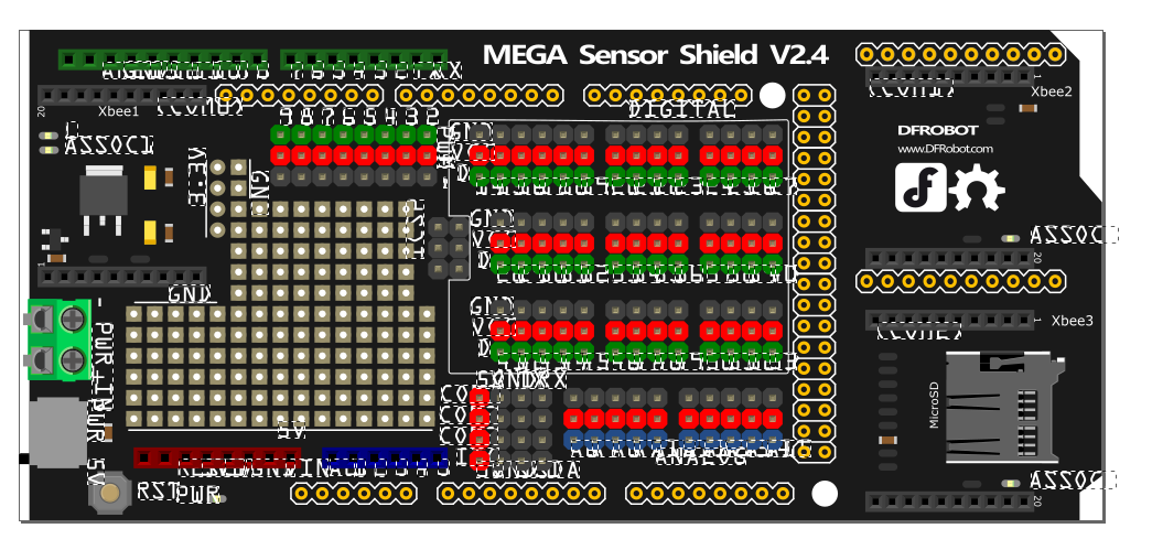
The red arrow in this image is where I would start pin0 moving horizontally across then up one line and repeating. but any arrangement that makes sense to you and has contiguous pins is fine. As well the two gold connector pads on the xbee connections are both unlabelled and don’t seem to appear in the (minimal) board documentation I have found. If you have a board, check if the pads or there and if so try and figure out what they do (maybe connect to the Xbee socket, but there are too many in the row to be one to one) as they will need connections in the part and don’t currently have them.
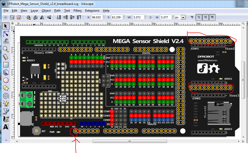
For the mega pads the easiest thing will likely be to load the Mega due in Fritzing and use either the printed pin labels or the “hover over a pin to get the description” function in Fritzing to get the name and pin number (in the due part) of the pin. You don’t need the description for the breadboard svg (nor really the due pin number but it may help later), just the association of Fritzing connectorxpin in the breadboard svg to the description for the fzp and the pin label in the schematic svg file later.

Edit:
while counting pins for schematic, I see the xbee connectors are likely 2mm rather than .1in and thus there are the same number of pins in the gold .1 pads, making it likely they are 1 to 1 with the associated xbee connector. Still worth verifying though.
edit:
I have just done a pin inventory (more of the mega pins are named than I first thought, only some are unamed.) What I am now thinking is that I may be able to write a python script to automate making the schematic. That would set the Fritzing pin number of the connectors in breadboard (since they have to match schematic) which reduces the work I need to do. If I do that first then you need to manually (unless I can see a way to automate that, which there may be) set the same pin in the breadboard svg to the connectorxpin defined in schematic. Same amount of work for you either way, but saves me a bunch of time. I’ll start connector0pin at the first pin labeled in the image above and go up in sequence, (except sequence will continue up the mega pins rather than horizontally as usual) so you can try setting the first couple of mega pins in breadboard to make sure they are set right, while I work on schematic.
edit3:
OK, here is a proposed schematic along with an explanation (which it needs ):

Now for an explanation: the svg looks useless because the boxes are too close together. The trick to that is this will be a subpart schematic so each box can be moved around schematic. That has a performance hit, but it looks to me to be the only viable option here, the part is too large. Each box has a label, so when moved you will still know what part it belongs to. At the moment this svg has no (or only a few anyway and those wrong) connector numbers because I haven’t added them yet (that is the next task) but should cover all pins in the breadboard svg (except the prototype area which don’t show in schematic typically, but will still need connector numbers in breadboard and the fzp file.) I’m open to suggestions on how to do schematic better if anyone has any!
P.S. Kjell identified the issue with uploading svgs:
the upload command sets the svg size too small (this one was set to
Robot_Mega_Sensor_Shield_v2.4_1_schematic|8x11]
so in the reply window here I increase that to 80x110 as below.
Robot_Mega_Sensor_Shield_v2.4_1_schematic|80x110]
Now you see an image of the svg and if you right click on it and select “save image as” the forum will download the svg (although it loses the name.) Progress!
Edit4:
It looks like I should be able to automate assigning the breadboard pins as well as schematic, if I am correct you won’t need to manually assign the pins in breadboard (which will save a lot of work!)
Peter
Peter,
When I open your file :
in fritzing, I got the error : “Fritzing only supports CORA and Droid fronts” and then
Edit :
I found a post where you put a link to download fonts and templates, what I did, but I don’t know how to include them into Inkscape.
Do you have a solution ?
Thank you,
Cécile
I’m actually surprised you get that much , this is an svg file not really a fzp so you need to download it, then remove the .fzp to leave
DFRobot_Mega_Sensor_Shield_v2.4_breadboard.svg
and then edit that with a text editor and remove the leading “remove_me” to create the real svg file, which can then be opened in Inkscape or another svg editor. However I’d suggest just ignoring it for the moment, as I found a way to automate assigning the connectors. At the moment I need to add 8 missing mega connectors in schematic and create the fzp file and we should have a complete part ready to go (or so I hope at least.)
Peter
Yes this is what I did, as you suggested above :
Then, in fritzing I took an IC part that I opened in the editor and then I opened the fzp file (the photo I put is just a screenshot of fritzing)
As you can see the writings are (/show/make? ) nonsense lol
Cécile
How are you loading the svg in Fritzing? At present this is only a breadboard svg, and shouldn’t load except if you load the svg in parts editor and that won’t let you change anything in the svg. You need to use an svg editor such as Inkscape or Adobe Illustrator to load and be able to edit the svg. At this point there isn’t anything much parts editor can do with the svg because it isn’t in a format that Fritzing understands (it lacks connector labels.) The font size change is likely because the font-sizes still have the px appended (I didn’t run the svg trhough FritzingCheckPart to remove the pxs because Inkscape will just add them back in again.)
Peter
Yes, sorry, I misspoke,
In fritzing :
- I took a ICs part, right clic, edit a new component
- I Loaded the image DFRobot_Mega_Sensor_Shield_v2.4_breadboard.svg
And this is how I got this image with weird font positions.
Cécile
OK, here is a new copy of the breadboard svg with the pxs removed. This should load correctly in to Fritzing:

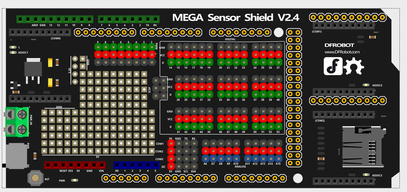
To get this one, right click on the image and “Save Image As” will get you the svg file. This loads correctly (although I see the fonts got substituted which I will correct) in Fritzing, but that still doesn’t help you as you can’t edit the svg in Fritzing. To edit the svg (which Parts editor at present can not do) you need to use an svg editor such as Inkscape (https://inkscape.org/) which will allow you to change the image and save it:

here are the connectors in detail:
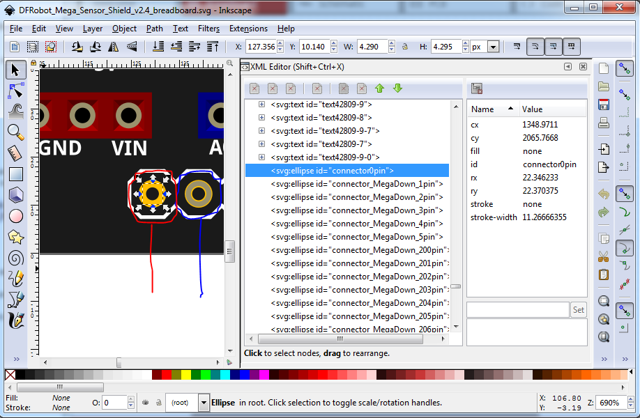
The connector circled in red is the only one Fritzing will currently recognize as it is in the correct format. The next one along (circled in blue) needs to change to connector1pin from connector_MegaDown_1pin. Normally I would have done that manually in Inkscape by changing the id field in xmI editor (the window on the lower right) but I now have a script that will do that automatically with the pins in this particular format (all at the bottom of the svg), so it no longer needs to be done manually. Hopefully I should be able to finish the complete part later today.
Edit:
Later today was optimistic. The pin numbering scripts worked fine and successfully assigned the pin numbers, but I screwed up the pin order between breadboard and schematic and now have to adjust that, so it won’t be finished today unfortunately,
Peter
Peter,
What I did :
- In inscape I opened DFRobot_Mega_Sensor_Shield_v2.4_breadboard.svg and changed the font to OCR A Extended (supposely accepted by fritzing).
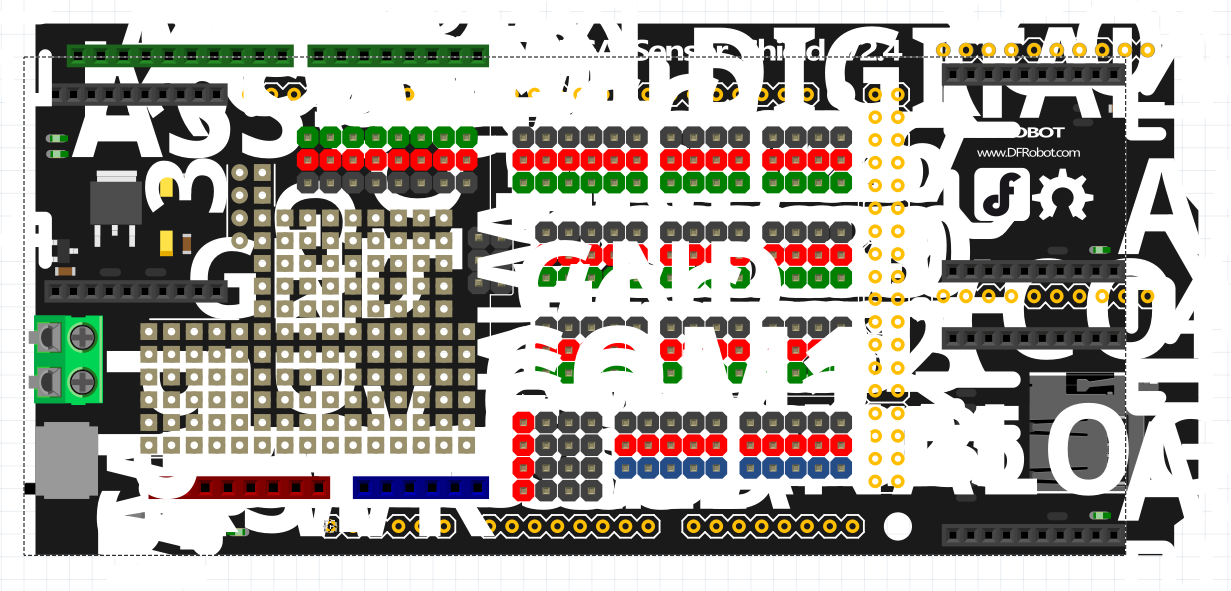
- Then, in fritzing I create a new component and loaded DFRobot_Mega_Sensor_Shield_v2.4_breadboard.svg as image but the font size was reduced (OCR A Extended font isn’t really accepted by fritzing) and was tiny, so I cheated in Inkscape and increased a lot the font size :
and finally the size reduced in fritzing was readable : I don’t know if it’s clear but now I got something I can work on.
Finally I make the connections in fritzing, but not all because the IC component doesn’t have more than 128 pins :
, but I have the ones that I need.
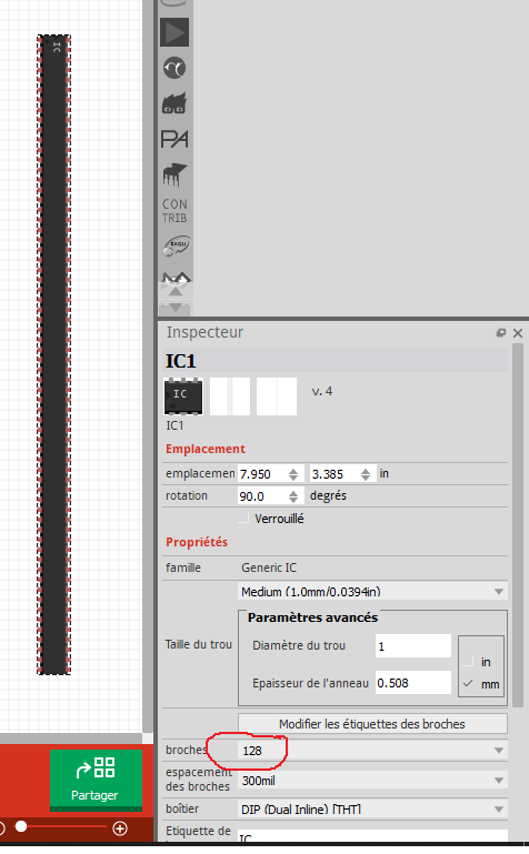
Update : I m stupid, I can change the number of pins in the component editor…
Cécile
The font I ususally use is “OCRA” (no extended.) The fonts Fritzing uses (and wants) are in the templates download zip file, if you haven’t already installed them. Its good that you have a part that does what you need, hopefully I will finish the full part soon. It has been and is worth doing because it has caused me to figure out some useful new tools for manipulating pins in svgs (which is the time consuming part on a part this large, some 534 pins in total assuming I haven’t missed any. To avoid font size problems, after editing with Inkscape edit the svg with a text editor and do a substitution (in vi which you may not have) :1,$s/px// Which globally deletes all values of “px” (so any edit command that does that should work.) The font size changes are likely caused by the px being on the font size (although Fritzing usually sets them to 0 deleting all the text.) FritzingCheclPart.py does this automatically on the way by.
Peter