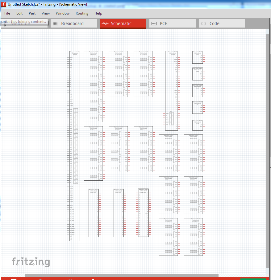
If your current part is working for you, I would probably stick with it, although you may want to try saving a copy of your sketch for backup, then do a “delete minus” on your part and try substituting the one above for it. In theory (for me practice has been variable ) this will delete the part but leave the wires. When you place the new par, you then need to click on the end of each wire (in each view) and move it slightly to make it reconnect (the connection should turn from red to green if you are successful.) I sometimes end up having to delete the wire and rerun it to make this work. As noted earlier this part uses schematic subparts (because the schematic is so large.) That means that you can click on any of the squares in schematic and move it independently of all the others. So if you are only using some of the connectors you can pile the others out of the way (even on top of each other) to save space. The part itself almost fills an 8.5 by 11in space (typically the larges it is easy to print) which is what made this necessary. Below is the schematic view of the default part. Note the boxes are too close together to actually make connections to most pins:
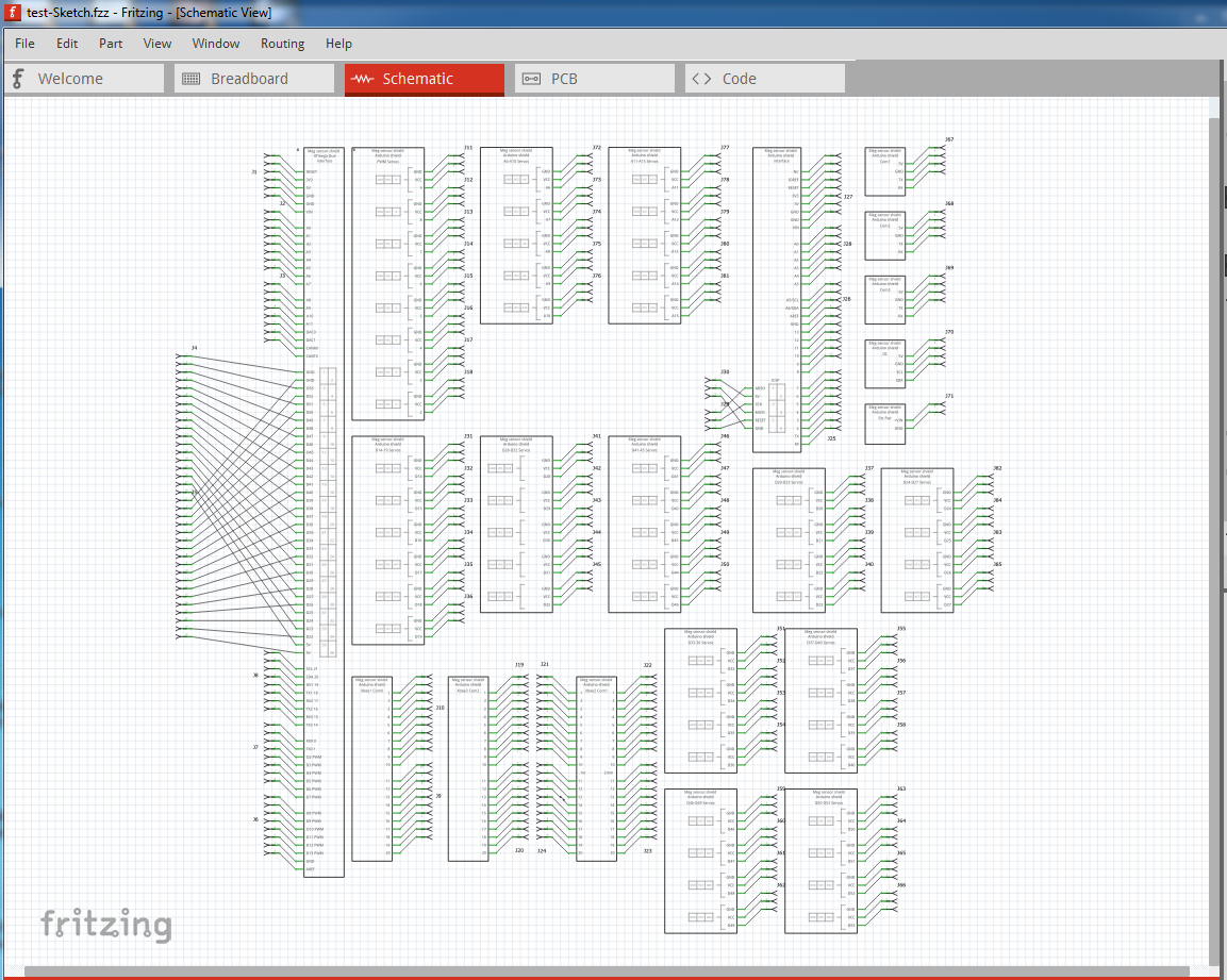
This is the schematic view of the test sketch where the boxes have been moved to allow connectors to be connected to them (to make sure all the connections go where I expected):
comparing the two you can see most of the boxes have moved from there original positions. As well, this part is designed to take the Arduino Due placed over the Due connectors on the shield. That should (but currently doesn’t, which I will investigate when I have some time) make the connections between the Due and the shield in schematic. At present because the Due has a different schematic from the shield that won’t be too useful. However an alternate Due part with a modified schematic that mirrors the one in the shield would produce the Due with all its connections to the shield automatically. A Fritzing bug (other than the current lack of connection probably due to positioning) means routing won’t show as complete in breadboard but it does work. Below is the test sketch that demonstrates the part connects correctly:
You are most welcome, but there is nothing wrong with doing only what you need done, as long as it works for you. I just like to make parts that could be put in to core parts (if I ever figure out how to run github properly ) and which I won’t have to rework when I finish the part checking script.
I have another question, I need to cable USB, HDMI, and other cables that don’t only have one wire (I don’t know if it’s clear). I would like to use a few wire, choose the two terminal connectors and get a cable. Do you know if there a way to do this ? I wish Fritzing implement this !
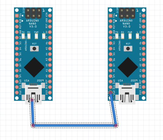
Unfortunately no, Fritzing has a function called buses, but unlike other EDA programs they are not multiple wires in a single conductor, but internal connections. So to do a real HDMI cable, your only choices are run all 18 or 20 separate wires, or if you only need the external function in breadboard, a single wire which represents the HDMI connection. Same for USB. Most Fritzing parts I’m aware of don’t have pins associated with the HDMI or USB ports. An obvious exception is USB connectors which do break out all the pins, but I expect you have a case where you need to show the connection in breadboard without necessarily reflecting it in schematic or pcb. Since a picture is worth a thousand words here is sort of what I mean with 2 pro mini parts. To make this work I really need to add a pin to the center point of the USB connector because you must anchor a wire to a pin (I don’t know of a way to make a floating wire, although there may be one). I would probably suppress schematic and pcb connections for that connector as they probably aren’t useful there. Doing that would allow the wire to go from USB connector to USB connector (rather than USB connector to pin as it does here):
It should be fairly easy to modify an existing part to do this for USB and HDMI connectors, just add an new pin to the center of the connector. I did this exact thing on the FRC RoboRio part in core parts with the USB connectors and ethernet connectors.
Hi Peter,
You confirmed what I thought.
Adding new pin to the center of the connector is exactly what I did until now. I’ll continue that way.
Thank you !
Cécile
 ) this will delete the part but leave the wires. When you place the new par, you then need to click on the end of each wire (in each view) and move it slightly to make it reconnect (the connection should turn from red to green if you are successful.) I sometimes end up having to delete the wire and rerun it to make this work. As noted earlier this part uses schematic subparts (because the schematic is so large.) That means that you can click on any of the squares in schematic and move it independently of all the others. So if you are only using some of the connectors you can pile the others out of the way (even on top of each other) to save space. The part itself almost fills an 8.5 by 11in space (typically the larges it is easy to print) which is what made this necessary. Below is the schematic view of the default part. Note the boxes are too close together to actually make connections to most pins: