Not enough information in any of these posts to do anything with. We would need a web site with physical dimensions and connector information as the template requests to do much of anything. Pictures are basically worthless (especially low res blurry ones!)
Peter
what can i add to get a heelp ?
A web site that describes the part you want that has the physical dimensions of the part and electrical connector information (i.e where are the connections physically and what do they do.)
edit
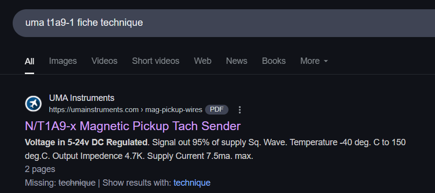
From this site
I would say there likely isn’t enough information available to do anything with. They look to be selling them and not providing connections or physical dimensions. Unless there is a better site somewhere you are likely out of luck.
Peter
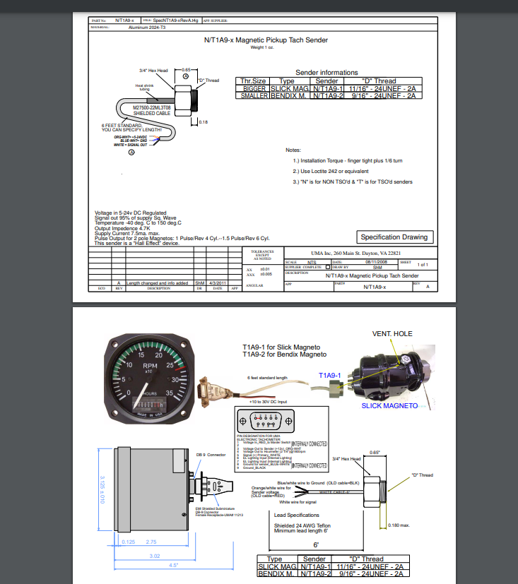
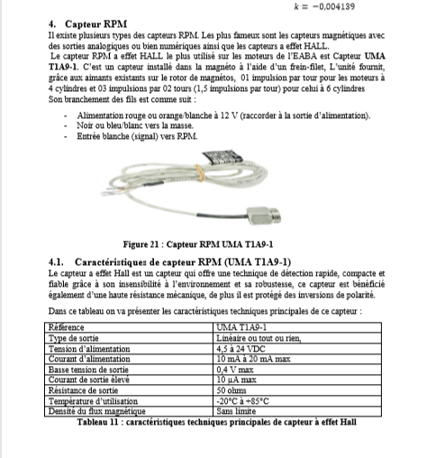
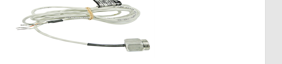
This if it was readable would possibly do. Can you supply the web site where you got this image from? The image itself is pretty much unreadable.
Peter
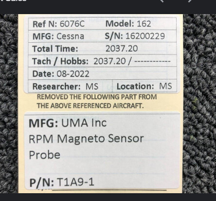
That helps somewhat. I assume you want the part circled in green (which is only a cable?)
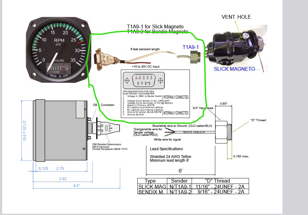
It is possible to make such a part but I am not sure what you would do with it since the cable alone doesn’t appear to have much use. What are you trying to do with Fritzing in relation to this I guess is the best question. If I know what you want to do I can probably tell you if it is possible or not. The things you are requesting appear mostly to do with airplanes which aren’t usually a use for Fritzing so an idea of what you are hoping to achieve would likely help us tell you if it is possible or not.
Peter
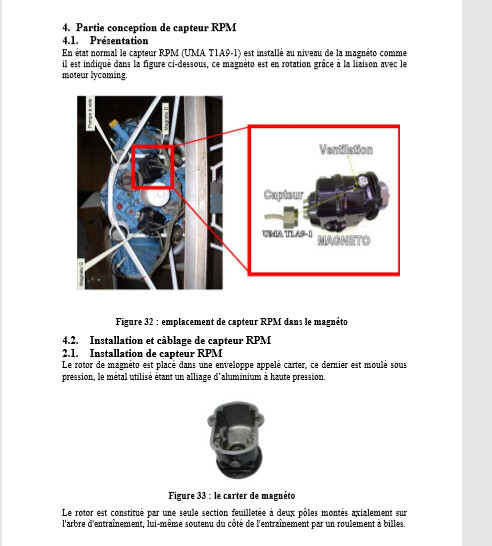
i want to get the sensor UMA to calculate the RPM of an airplane and i want to make a prototype, but first i want to make the electrical schematic of the sensor with arduino.
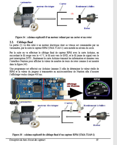
OK, I think I see what you need, presumably the arduino will replace the tach dial in the above image, so you want the connections to come in. The easiest I think would be a 3 pin header which would in your prototype connect to the cable to the tach like this
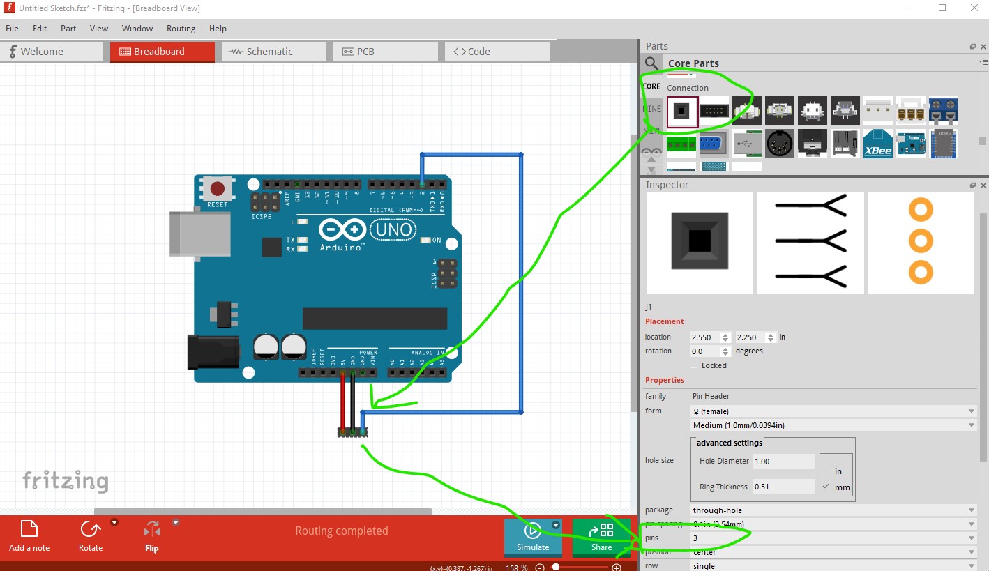
drag the header in to the sketch, then set the number of pins to 3 (in Inspector the bottom right window) and connect power ground and signal to the arduino. In schematic
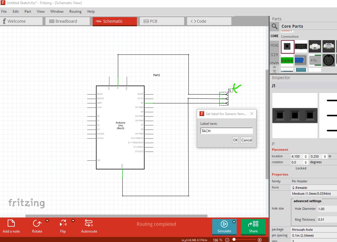
right click on the J1 label and select edit which will allow you to set TACH as the name to indicate the tach is connected there (as it will be in your prototype.)
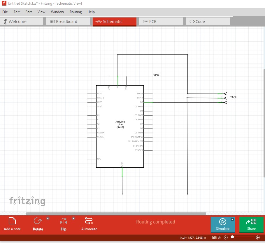
You can then add parts such as a display or whatever else you need and prototype your project. The same thing should work for other sensors that you need as they will presumably also come in as wires. That should let you prototype your project without needing new parts I think.
Peter
thanks but i want only a visual schematic and i will make my prototype with other sensors cause the VDO not available on my country.
So you only want breadboard view and with an image of the real device connected via the cable?
Peter
yes with arduino mega 2560 but the breadboard is not necessary.
But you want the sensor to appear as itself in breadboard view (as opposed to appearing in schematic?) I can make a part that will do that if that is what you need.
Peter
OK, I’ll make something that does that.
Peter
okay thanks man i appreciate.
OK this part should do what you want.
T1A9-1.fzpz (3.9 KB)
It looks like this
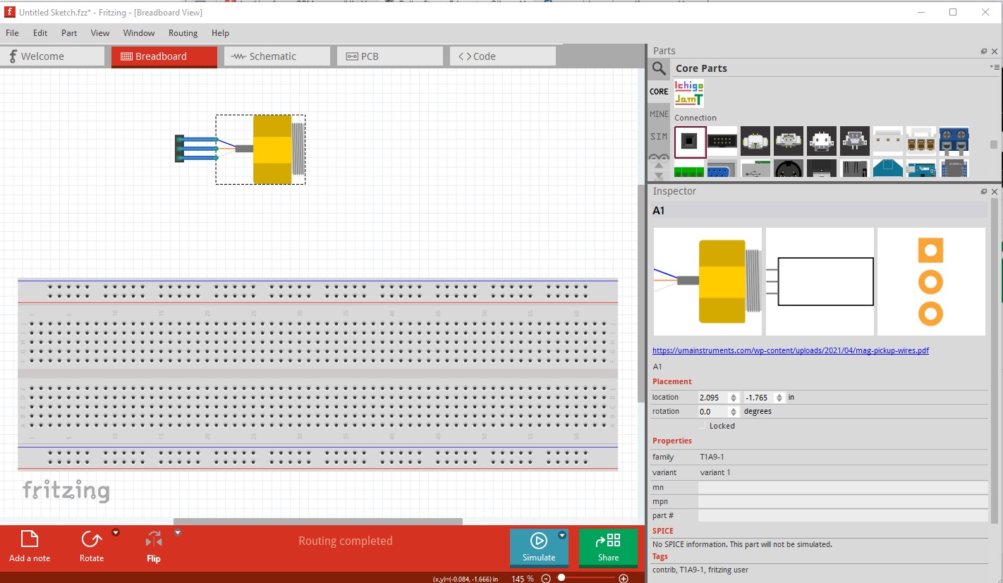
and has all three views (pcb is basically a 3 pin header for either plugging in to or soldering wires to as you choose.)
Peter