I’m trying to load a new image for silkscreen only, but the image comes up w/ black background. Fritzing logo has same look when placed on PCB- like a photo negative. Is there background setting I’m missing?
Thanks,
Jim
Where are you trying to upload the silkscreen? In the parts editor? In a part, silkscreen is part of the pcb image. It can not be loaded separately from the rest of the pcb (copper pads).
The (I think) screen shot image you provided does not tell much. The actual silkscreen image and part would be much more useful as information that can (maybe) be used to tell what the problem is.
If you mean loading an image for for a pcb object, that is different, but still need to see the actual file being used to tell if/what problem it is with the file, and a way to correct it.
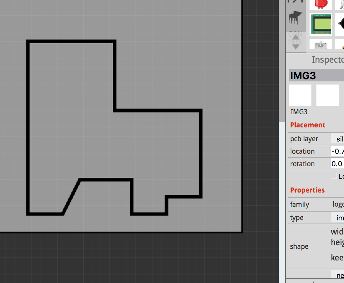
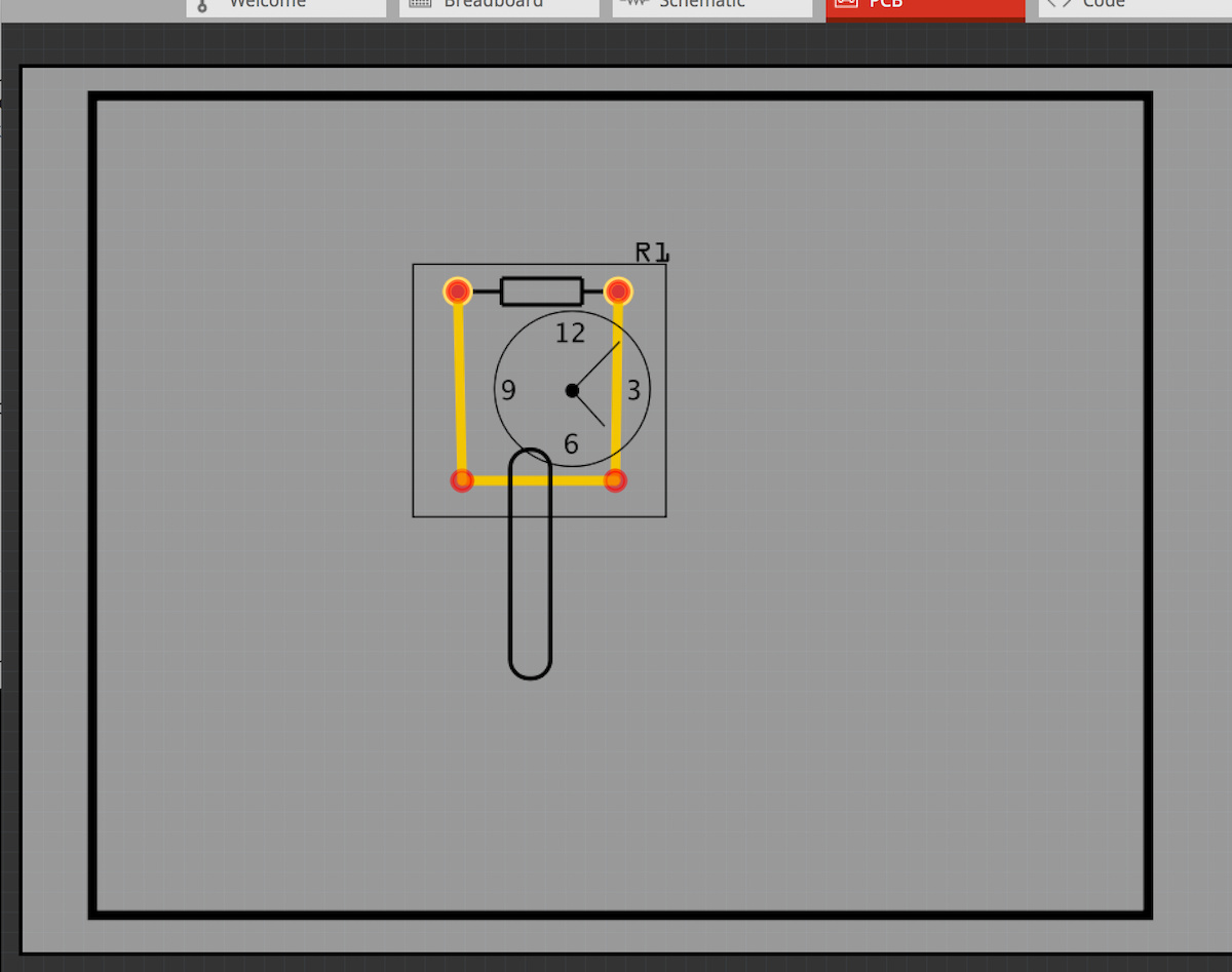
I’m trying to load image under Core parts- PCB view- Silkscreen Image-Part Inspector- load image. When I drag the Fritzing Image over to the PCB workspace, it looks like the above screenshot.
When I design something w/ my CAD software as an image (like gray image above) then export jpeg- it comes in w/ black background, just like the Fritzing logo…
I’ll try reposting the CAD pic here as jpeg.
Hope you can download this, mM
Thanks,
Jim
Well, apparently not…
My cursor doesn’t give the option like it does the Fritzing PCB jpeg to download.
So 2 choices:
- Screen shot copy & paste for file download & possible integration w/ help
- I’ll just be happy with my current scaled text letter ‘o’ as symbol for stand up axial cap-lol
Jim
ps. Tried to go into ‘parts editor’… but never had much luck accomplishing anything- nothing would save as a change into current screen
Is that jpeg image from both the original post, and your explanation comment the actual file you are trying to upload?
I have never (before) used the silkscreen image part, but from different contexts I have some observations.
That image has grey lines. Solid color, on a solid (or no/transparent) background might work better. From symptoms, the grey sections are being treated as transparent (no silkscreen), and the white areas as the (black) content to add to the silkscreen on the pcb. Try white graphics on a black background.
My test load shows a lot of what look like jpeg artifacts. Thin white lines on the black background. PNG might work better. The file will probably not be as small, but should avoid that kind of problem. Maybe a simple 2 color gif file.
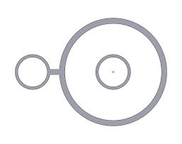
The graphics for the silkscreen is quite simple. Probably even better (my first choice), would be to use an svg image. It looks like that could be easily created with 4 circles and a line. A bit harder, but a single path would do as well containing nested cutouts for the inner circles. SVG files scale way better than any of the bit map formats.
Parts editor does not save into the current screen. It saves to a new part file, which could then be placed (from the “MINE” bin) in the current sketch. Or saved, and used in other sketches, or exported and published for others to use as well.
TLDR. It’s because it’s a raster image, ie, jpg, it needs to be a svg.
![]()
I did a rough conversion in Inkscape so you will have to redraw it in a svg editor, but try this one as a proof of concept.
Or this svg, which is much simpler and smaller. 0.5K versus 86K.
![]()
I confirmed that either of the svg files loads fine. I assume that what @Old_Grey posted is from a raster to vector conversion program. I built it from scratch, aligning by eye to a 4 times zoom on the jpeg image.
“That image has grey lines. Solid color, on a solid (or no/transparent) background might work better. From symptoms, the grey sections are being treated as transparent (no silkscreen), and the white areas as the (black) content to add to the silkscreen on the pcb. Try white graphics on a black background.”
I will try the double negative-
Also-
tried other file types… specifically .png, .svg, .bmp- all with same result… but which way are .svg files more simple? From an ability to import existing file within Fritzing? Or manipulate?
Ah-
Got it with the parts editor explanation…another segway as alternate path- lol
My cursor doesnt allow download of this (either) image posted by you or mM
But perhaps a different path-
I dont want to spell out my email address here due to potential spam- but I do have public website for my Race Car Parts which has my address on contacts page, if so kind, please email files to listed address on ‘contacts’ page at top navigation bar.
Thanks in advance,
Jim
How come you can’t right-click “save image as”?, that’s how I got your jpg.
Maybe open image in new tab and save it.
Are you working from a cell phone, or a tablet that does not have a mouse? No touch pad with right and left buttons either? Browsers typically used for a touch screen system provide alternative ways of getting the ‘right click’ to display the context menu needed to download (save image as) an image from a web page. Try tap and hold for a few seconds on the image.
You said your cursor. Are you working with a screen reader, or a text based web browser? All control is from the keyboard?
Right click the area does allow download… didn’t try before because the cursor doesn’t identify the file when crossed, like it does over Fritzing jpeg- my bad.
Now back to primary Q-
Why this background shading issue w/ imported images? Shouldn’t this be simple procedure?
Jim
The silkscreen is not really an “image”. The way fritzing uses it, it is a mask. It is only used to show where silkscreen exists, and where it does not exist. Black (actually anything other than white) means no silkscreen, and white means silkscreen. Think of it like a stencil. If you have ever use masks in Inkscape, it is the same concept.
Thanks mM,
You answered my question- path of least resistance is to go with what I currently have.
Jim
Make sure you check the gerbers so that the logo is actually is coming out right.
There’s a stock part called “silkscreen Image” that loads SVG.
Example shows three of them:
Watch in box
Oblong
Big Rectangle
They are transparent fills so everything shows behind them and the dimensions are correct.
Yes,
That icon in PCB view is what I’ve been using to load images- but how did you created the pic above?? I drag Fritzing logo over to PCB workspace from that icon, then modify in Inspector by loading Image- thats what produces issue w/ shading on jpeg, bmp, png, or svg of same file import.
Jim
You can not use jpeg, bmp, png, only svg. svg’s are nothing like raster images, they are xml code that is drawn when opened, ie, vector graphics. Think of it as digital, either it is a solid block of colour, or it’s not there, ie, it can’t be half way like analogue. Basically it shouldn’t have fuzzy edges like a raster image, so it’s probably not a svg image.
MM svg works fine in FZ, ie, no fuzzy edges, it just when you gerber it it’s not right. Hence why I posted the vid link.
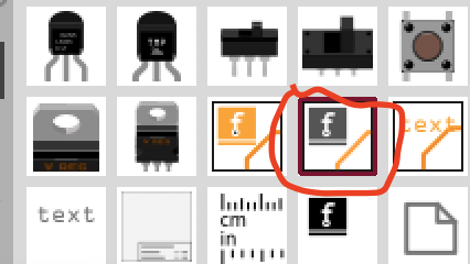
Load your svg with the 7th button in the tool bar. If it doesn’t load change the svg extension to .fzpz and upload.
Unfortunately this no longer works with the new forum software. It detects the svg in the .fzpz and tries to render it. These days you need to actually zip the svg in to the .fzpz and upload that.
Peter
Tip’s
• The Drawing is Not colored
• No Layers to make - they get made when saving your drawing as plain SVG.
• Some programs have saving options - check them out to see what works for you.
• Some programs embed XML items that Fritzing doesn’t like. Check and delete them, if needed.
I make the SVG’s using different programs - usually with EZDraw and Inkscape but, others, too, including FreeCad.
I just drew one (screenshot below) in Inkscape. Saved as Plain SVG and loaded it into Fritzing.
Screenshot of svg/XML text Reflowed it for easier reading. Didn’t bother to delete header stuff/etc.