LdLidar_LD03.fzpz (20.1 KB)
Very simple first mock for a LdLidar LD03 or similar models like the LD14 or LD14P.
I´ve just created the Breadboard view.

LdLidar_LD03.fzpz (20.1 KB)
Very simple first mock for a LdLidar LD03 or similar models like the LD14 or LD14P.
I´ve just created the Breadboard view.
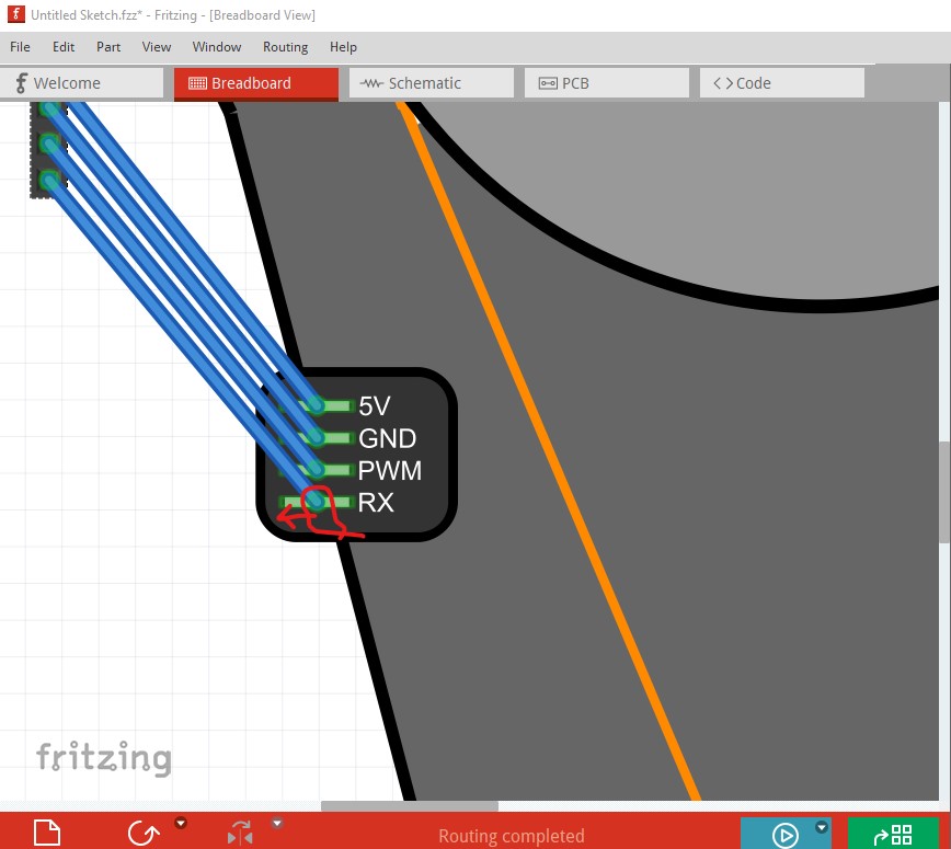
You need to add terminalIds to your breadboard svg (or reduce the pin to a rectangle at the end of the pin.) At present the wire connects to the center of the pin (which is wider than it is tall.)
it would also be good to either suppress schematic and pcb of use Randy’s Inkscape extension to produce a schematic. How to do all these things are covered in this tutorial.
edit:
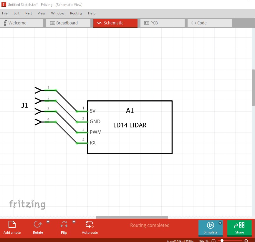
I fixed up your part (it had more problems than I initially saw!) Breadboard was missing the layerID which will cause the part to not export as an image, as noted it needed terminalIds to work correctly and the pins weren’t on 0.1in boundaries. I added a schematic (made with Randy’s Inkscape extension) and modified the .fzp file to add the necessary definitions and suppress pcb view to create this new part.
LdLidar_LD03-improved.fzpz (7.0 KB)
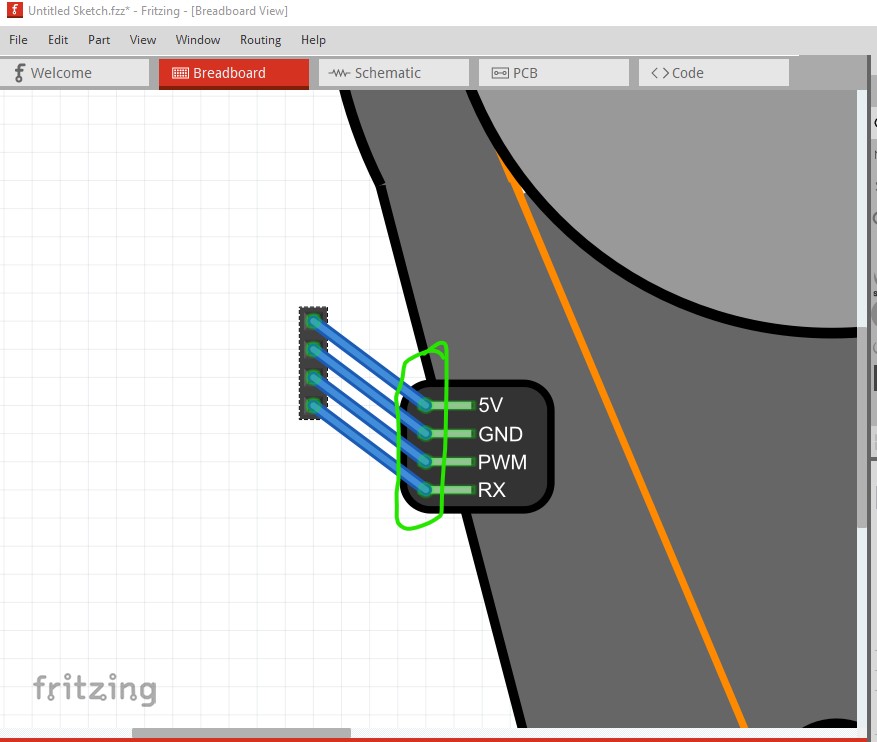
because of the terminalIds in breadboard the wires now connect to the end of the pin as they should.
schematic (I also changed the label to be A for assembly!)
This part has a new moduleId and so will load alongside your current one for comparison.
Peter