Introduction to fritzing + tutorial (by Raptor)

(Note: All these have been tested with fritzing 0.9.3b)

Hello and a very warm welcome to Fritzing for those who are new to it!


How to use Fritzing

When you open fritzing, you will get to the welcome page

In fritzing, there are three views - Breadboard, Schematic and PCB. At the right side, there is a window that says “parts”

This where you will be taking the parts from.


Breadboard view

When you open the breadboard view (by clicking the “Breadboard” button"), you will see this:

image

By default, the breadboard will be there, so you can either use or delete it (by pressing the delete key).

To use the parts for your sketch, drag and drop the part from the parts palette.

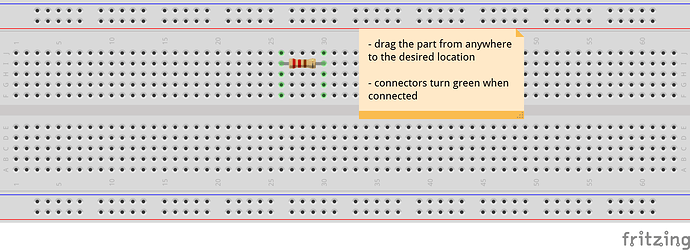
  1. The example below makes use of a resistor

You can connect the resistor to the breadboard by dragging it to one of the terminals in the breadboard like this:

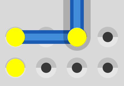
  1. Changing and bending the leg for bendable leg parts

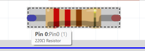
Some parts have bendable legs (e.g. resistor, LED, capacitor, etc.) and it is possible change and bend their legs

You can do so by…

  • hovering your mouse over the end of the leg (coloured in red when not connected to anything). Then, the terminal turns blue and a symbol appears
  • left click + drag the leg to your desired location
  • (optional) hover your mouse over the center of the leg, then, drag the turning point to your desired location (it’s coloured in a darker shade like in the pictures below)
image

  1. Adding wires

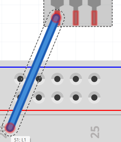
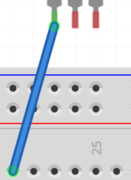
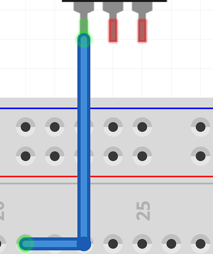
You can connect component to component with wire(s), and you can do so by:

If you want to change the turning point of the wire, you can

  • hover your mouse over the turning point (the turning point turns blue
  • left click on it (it will then turn yellow) +
  • drag your mouse to your desired location
  • done!

Screenshot 2024-12-02 215420
Screenshot 2024-12-02 215434
Screenshot 2024-12-02 215453
Screenshot 2024-12-02 215501


Schematic View

You can open the schematic view by clicking the “schematic” button

When you open it, you will realise that there is nothing. This is because some parts (like a breadboard in this case) only have one or two views.

Similarly, to use the parts for your sketch, drag and drop the part from the parts palette.

Wiring up the parts is quite like doing it in the breadboard view. However, in the schematic (and PCB) views, you can connect wires at a junction. It’s easy! Just connect the wire to an existing turning point.

Untitled Sketch_schem

CAUTION: THIS ONLY APPLIES TO SCHEMATIC AND PCB VIEWS! IT DOES’NT WORK IN BREADBOARD VIEW. THE PARTS IN BREADBOARD VIEW WILL NOT BE CONNECTED TOGETHER LIKE IN THE DIAGRAM ABOVE!

(work in progress)

(edit from post above)

Breadboard View add-in

You can add text to your sketch in breadboard view. Just:


You can change the colour of (the) wire(s) too. Just right click on the wire > wire colour, then select your desired colour.


Schematic View add-in

Just like the breadboard view, you can add text too.

Steps are similar, except that this time, drag the part from the core bin > schematic view


(continued from post above)

PCB View

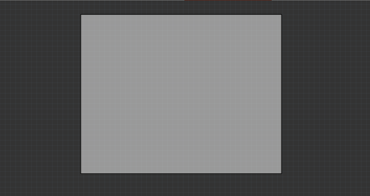
When you open up the PCB view, you will see something like this:

You will notice that there is a huge rectangle in the middle. This is your resizable PCB. You will be putting all your components in this PCB. Such an example would be:

example_pcb

You will also realize that there are new tools in the parts palette for pcb:

image

Don’t worry if you do not know how to use any of these parts. I’ll be covering the purposes of these parts.

1. Rectangular PCB - Resizable

This part is basically a PCB board. You can resize it to your desired dimensions by clicking on the part, then left click + drag ⌜,⌝, ⌞or⌟ to resize the Rextangular PCB part. You can also key in the desired width and height in the inspector like this:

One reason why I don’t really like the interface is that the units are in mm.

If you are not used to mm (like me because I prefer the grids set to 0.1 inch), then convert the inch to mm.

Google is your best friend. Just search “inch to mm”, copy and paste the mm values into the inspector, and… Done!

2. Jumper

The jumper part allows you to place a real wire between two connectors.

3. Silkscreen Text

This part allows you to add text to your PCB.

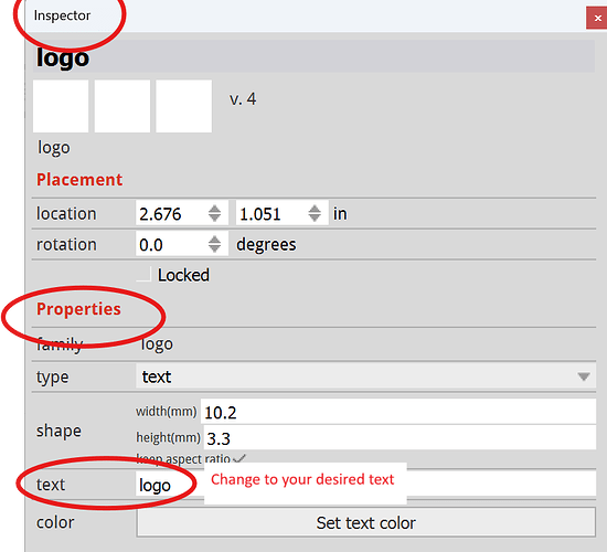
Just drag the part and place it on the Rectangular PCB, then with the Silkscreen text part selected, go to inspector > properties > text and change “logo” to your desired text.

4. Silkscreen Image

This part allows you to add a silkscreen image

Just drag the part and place it on the Rectangular PCB. If you want to change the image, select it, go to inspector > properties and select an image from the dropdown menu, and change it to your desired image. You can also load your own image file. If you do, you should look at this post

5. Hole

This part allows you to have holes in your board.

Just drag the part and place it on the Rectangular PCB. If you want to change the size of the hole, go to inspector > properties > hole size and select from the dropdown menu your desired size. If your desired size is not available, then key in the hole diameter and ring thickness in the advanced settings.

6. Via

This part allows a junction between a wire from the bottom layer (coloured in orange) and a wire from the top layer (coloured in yellow). Here is one such example:

pcb

The next few parts are my “never ever used” parts, so to be honest I have no idea how to use them. I will edit this post again once I find out more information, so I’ll skip them first.

Things that you need to know

There are a few important things you need to know for the PCB view.

  1. Moving wires to different layers. Just right click on the wire > move to bottom/top layer.

  2. View from ____. You may need to know how to view the PCB from different perspectives. Just press “view from above/below”


For all views

1. Adding Notes

Creating a note can only be done when you are only in breadboard/schematic/PCB view.

The ways of creating a note are stated in this topic.

  1. Go to edit > add note
  2. Press the “Add a note” button in the red section on the bottom of the app

  1. Drag the note part from the core parts

This is incorrect. If you click on the edge of a jumper you can change the length of a jumper like this:

It would also be useful to be using the latest version of Fritzing which is 1.0.4 currently, 0.9.3B is very old (from 2016) and there are many fixes in the newer versions.

Peter

Thanks a lot, Peter!