Hi, here my self-made part :
IN-14 Nixie.fzpz (38.6 KB)

Actually I’m working on :
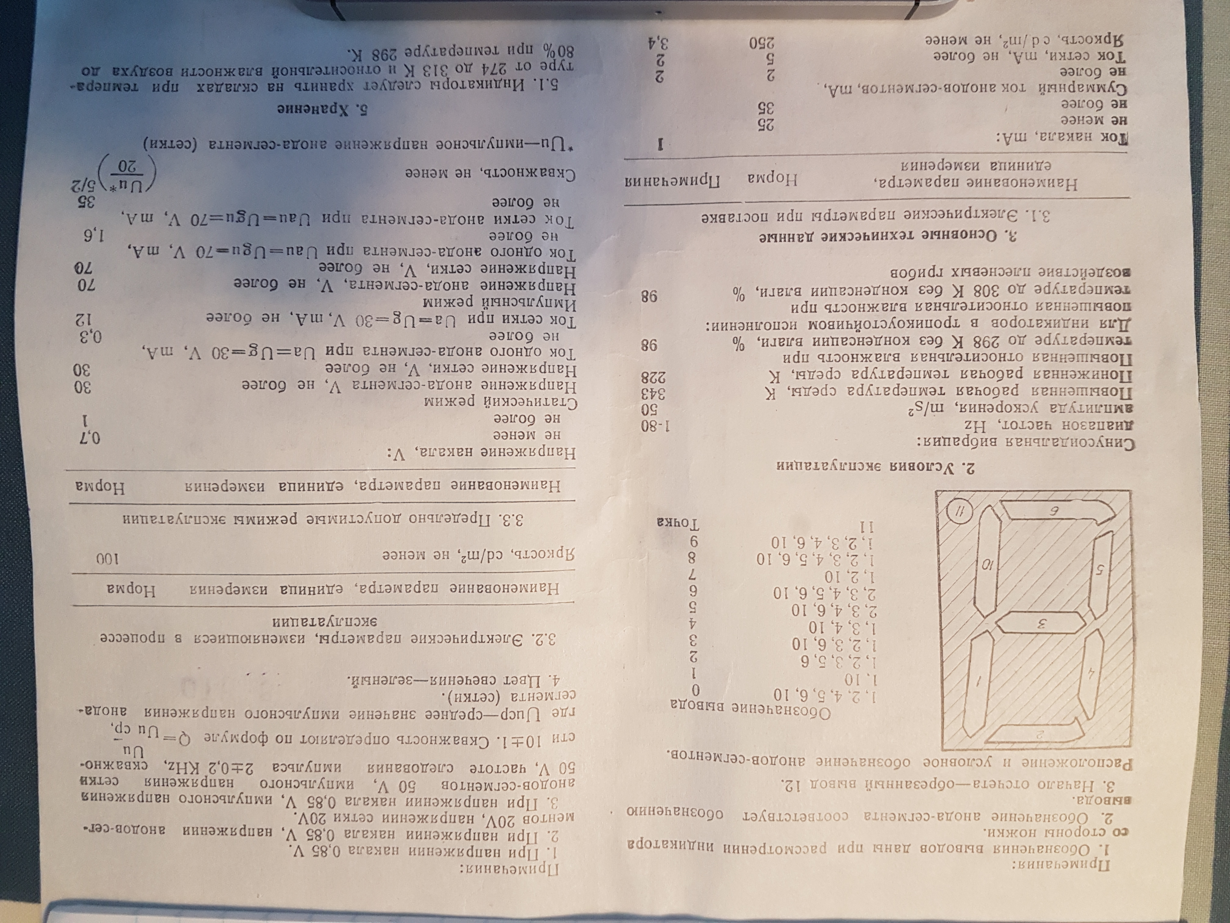
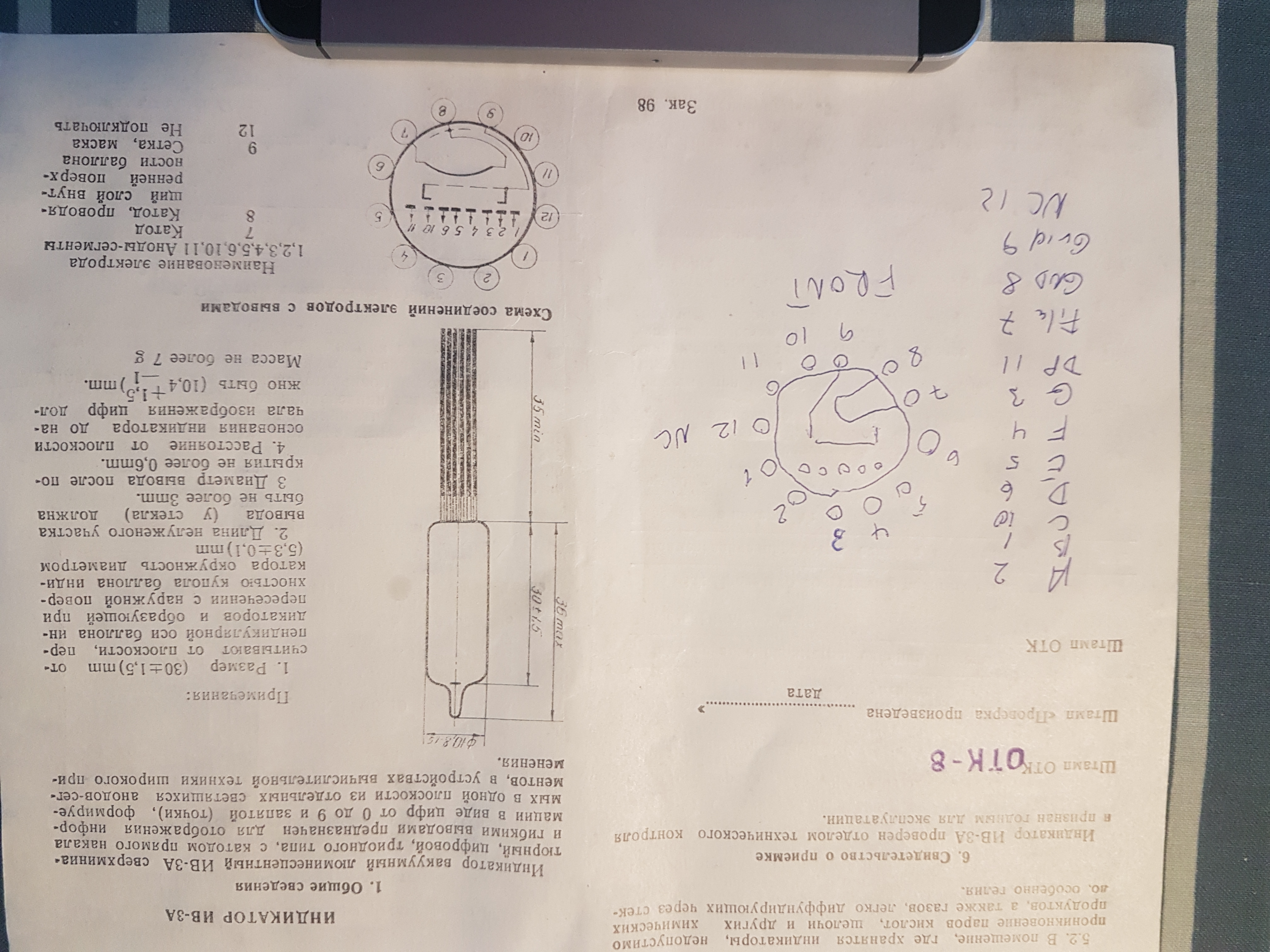
- VFD TUBES IV-3 NIXIE
- VFD TUBES IV-8 NIXIE
Hi, here my self-made part :
IN-14 Nixie.fzpz (38.6 KB)
Actually I’m working on :
Hi Brisfan,
Any progress on the IV-3 part yet? I am new to fritzing and trying to design a pcb with 4 or 6 IV-3A tubes. Tried to modify your IN-14 part in the parteditor, but gave up…
Any help would be highly appreciated.
If you post a pointer to a data sheet for what you want one of us could probably modify the above part for you. A quick search didn’t find me a data sheet with a mechanical drawing and pin out though.
Peter
Hi Peter,
Thanks! I managed to make a prelimary part - almost finished hope you can finish it. I will upload two fotos of the original datasheet (in russian), including my notes. The front of the tube is the direction of pin 9.
I am not sure if the photos are too large, otherwise PM me and i can email them to you.
BR
Ejnar
One more thing. I deliberately used a diameter of 10 mm for the ring of pinholes in order to make space for a 5mm LED in the center. The actual diameter at the base of the tube is 6mm.
OK, I’ll have a look at it and try and complete it.
Edit: here is an improved part:
IV-3A VFD tube.fzpz (8.8 KB)
I didn’t change moduleId so you will need to delete the old part in order to load this one. Breadboard has the tube (sort of) there to be closer to real life. Schematic is totally new. Pcb had the terminalIds removed (they aren’t needed and may have caused a problem!) Note the pad’s holes are 0.038in (.1 in header post size.) The hole / pad size may need to be smaller for sufficient clearance due to the voltage and/or the size of the pins (which likely isn’t .1in header size!) Assuming you are using Inkscape to edit the svg the hole size will be hole size = pad diamater - (2* stroke-width) . The current case is 0.078in pad diameter, and 20 thou stroke width giving a 0.038 hole. To reduce them, set the pad diameter you want and then note the resulting radius value in xml editor. Now undo the diameter change and using xml editor change each pins radius to the new radius value. This keeps the x/y position of the pad constant while the diameter changes.
Peter
Thanks a lot, Peter! I will try to produce a print asap😁
BR
Ejnar