Hi there,
I use Fritzing to design learning material to teach Arduino to beginners.
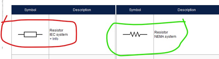
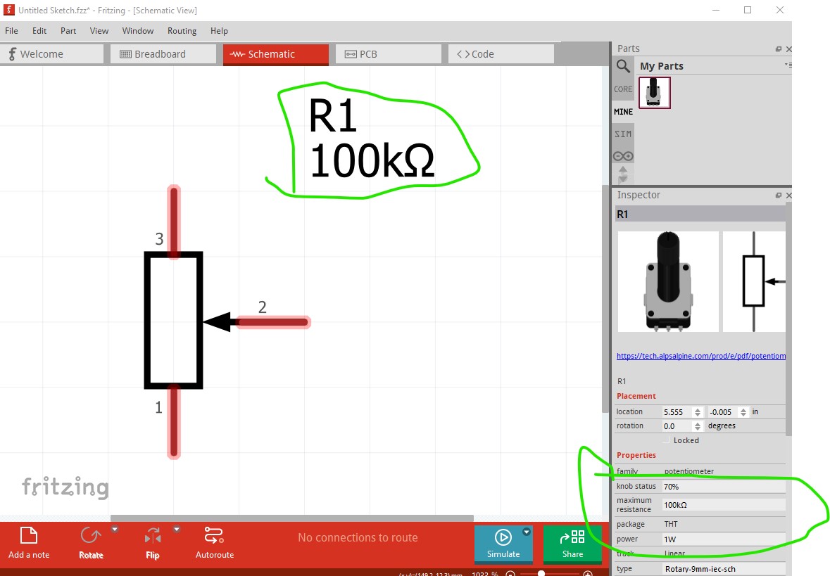
One thing is problematic: how can I have IEC (a.k.a. euro style) schematics symbols for resistors and resistor-related (e.g. potentiometers)?
Even for the most basic of these (those in the “basic” catergories) I can’t find the option to change the zig-zag to the rectangle style.
What did I miss?
Thanks for reading!
Matth.
1 Like
I don’t think Fritzing currently supports the IEC format (circled in red here) only the NEMA type symbol.
you could make a custom part for it, but the Fritzing resistors have special code that provides the color bands and that probably won’t work on your custom part.
Peter
Currently, IEC-style symbols are not supported. There is a request for them in the bug tracker:
@vanepp , the special code is triggered if the module ID of the part ends in “ResistorModuleID”. So, if you make a new part with a moduleID of, for example, IEC_Style_v0_ResistorModuleID, (I think, did not test it) that the part should work OK.
Thanks for the replies!
It’s quite puzzling why such a basic feature wasn’t included from the beginning.
If I make my own IEC versions of the parts, I’ll try to share them on the forum.
2 Likes
Parts editor currently doesn’t support editing bendable leg parts so I will have a look at making a IEC resistor part (as it is somewhat complex if you aren’t familiar with making parts…)
edit:
Not as easy as it should be. This part does most of what you want, but won’t change the resistance value in Inspector and I don’t know why.
edit1:
figured out why. The moduleId (unlike most of the others) wants prefix extensions not postfix. This fixed part now looks to work correctly and set the resistance in Inspector as expected.
resistor-iecschematic.fzpz (3.1 KB)
Peter
1 Like
Will you also add potentiometers etc?
I might if you provided documentation on what you want them to look like (preferably from a standards doc if there is one.), what you want and there aren’t to many of them.
Peter
Just replace the zigzag with rectangles…
But adding new components for this, is actually a very bad programming practice. Each existing component should have an “icon” property that can be selected, like in most other circuit software programs.
This part should do what you want.
edit: Nov 27 2024
Not quite, the moduleId was incorrect so replace the part with a working one.
Rotary-Potentiometer-iec-sch.fzpz (15.2 KB)
Peter
1 Like
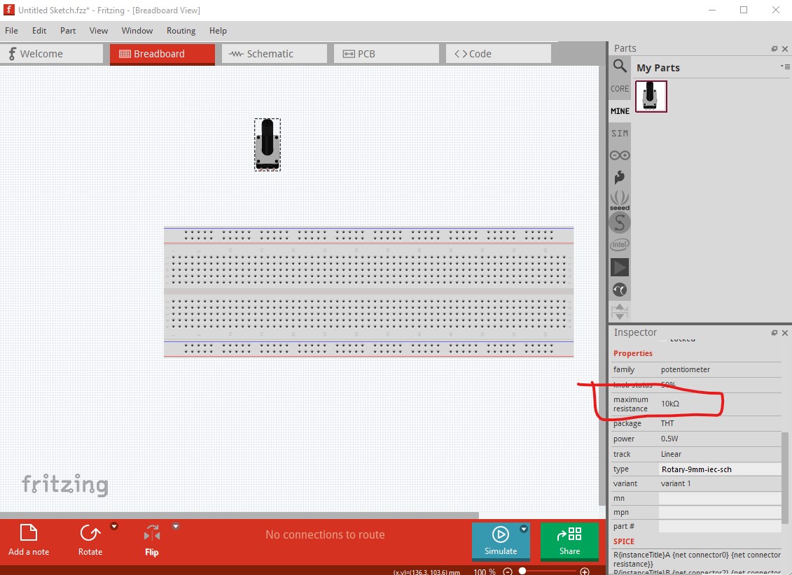
OK, but I can’t change the resistance… Or am I doing something wrong?
No I screwed up the part definition somehow. I will have a look at it (I thought it was correct but it doesn’t appear to be.) The changeable fields are greyed out which indicates the part config is wrong somehow:
changing to the standard 9mm pot works correctly.
Peter
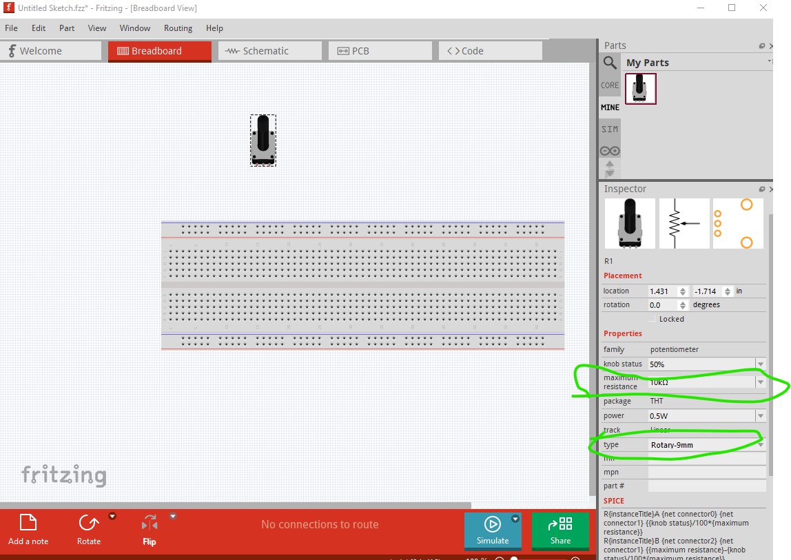
I just replaced the part with a corrected version that appears to work (the moduleId wanted more characters than I provided.)
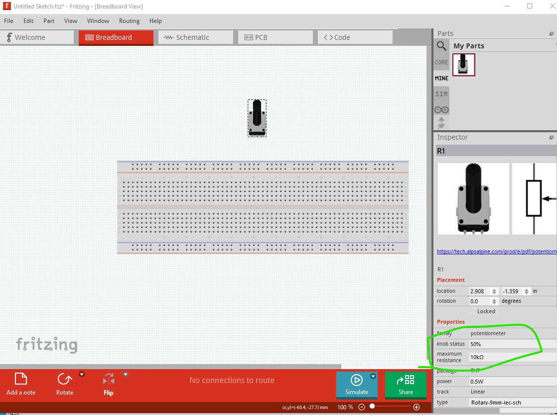
and the value (and other parameters) now are changeable.
Sorry about that.
Peter
1 Like
Hi Peter
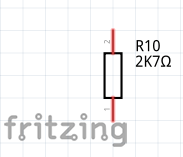
This info has been very helpful to me today. One thing I haven’t figured out yet - having changed my schematic symbol to the 1:3 rectangle, I can’t see how to change the value designation from (say) 2.7k to 2k7
Using the multiplier in place of the decimal is pretty much industry standard these days, I think.
Gerry
My bad.
IEC 60062:2016 specifies that the multiplier should be in upper case, 2K7 not 2k7 as I wrote earlier
OK. Typing 2K7 (not 2k7) in the Inspector field allows me to use multiplier as decimal (solved).
Now, how do I lose the omega? ![]()
You don’t. Fritzing will use (SI) units (like Ω Ohms) just to be clear. Reason being there are multiple units of resistance that exist…
(I don’t have my COM with me now, but I’ll double check later)
Confirmed, you can’t lose the Ω
Thank you for trying to help, Raptor. I appreciate your efforts.
I have added my comments to the existing issue on github:
I am no coder, but I tried (failed) to make sense of the parts file format in the wiki:
2.1 Part file format · fritzing/fritzing-app Wiki · GitHub
Basically inside the .fzpz file (a.k.a. fritzing part sharable file, which is a zipped file) contains this:
[part_name].fzpz
| part.[moduleID][part_name].fzp
| svg.breadboard.[moduleID][part_name].svg
| svg.schematic.[moduleID][part_name].svg
| svg.pcb.[moduleID][part_name].svg
| svg.icon.[moduleID][part_name].svg
Sure, and I searched through each of those looking for a reference to unicode 8486 (the omega symbol) so that I could remove it by way of an experiment. Unfortunately, I failed to find anything I could modify.