Not bad but a couple of errors. In schematic your pins are not aligned to the grid the bottom two on the screw terminals need to move down a bit so they line up with the grid. If you are using Inkscape Randy’s schematic extension makes creating correct schematics much easier.
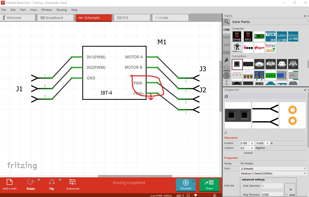
in older Fritzing versions (this is 0.9.3b) it will show up like this
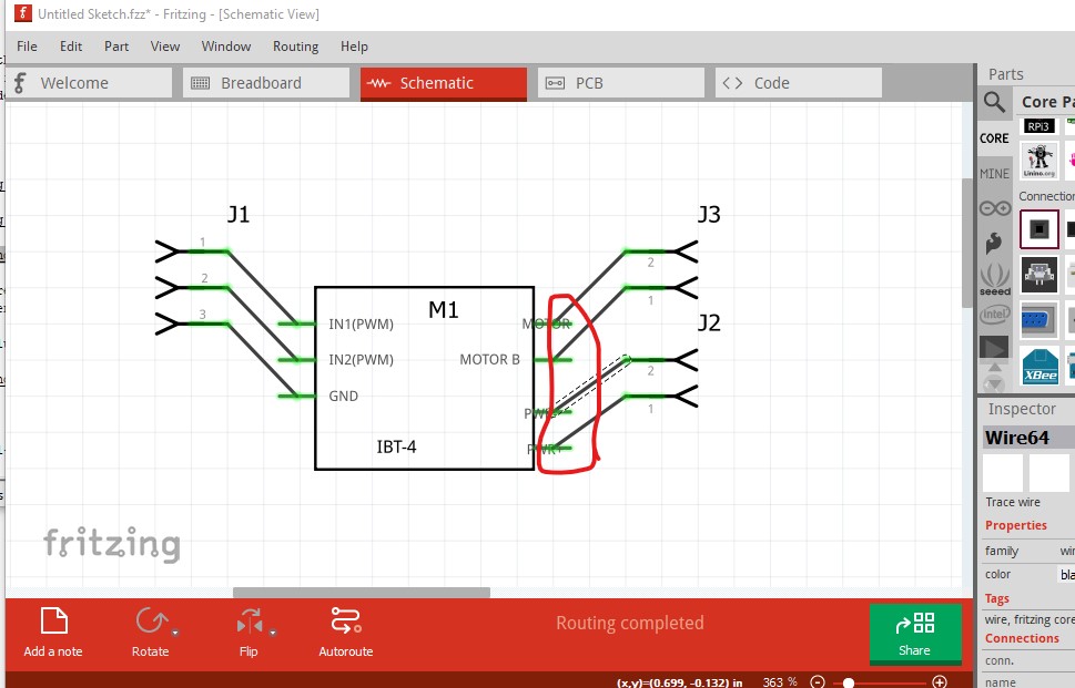
the wire will connect to the center of the pin without a terminalId.
In pcb it would be preferable to suppress pcb view rather than have an error (the red rectangle indicates undefined pins.) That can be achieved like this:
replace this in the fzp file (you have to edit the file with a text editor, parts editor can’t do this)
    <pcbView>
      <layers image="pcb/IBT-4_53a3a90fa93f6c95b7b83e4ac43a0268_46_pcb.svg">
        <layer layerId="silkscreen"/>
        <layer layerId="copper0"/>
        <layer layerId="copper1"/>
      </layers>
    </pcbView>
with
    <pcbView>
            <layers image="breadboard/IBT-4_53a3a90fa93f6c95b7b83e4ac43a0268_46_breadboard.svg">
        <layer layerId="breadboard"/>
      </layers>

    </pcbView>
which reuses the breadboard view as pcb (which won’t render in pcb) suppressing pcb view. Fritzing requires a renderer in pcb to function. As well your connectors need a terminalId (it isn’t deadly current versions of Fritzing insert them if they are missing) in schematic view (but not in pcb view as here)
    <connector id="connector1" name="IN1" type="pad">
      <description>IN1</description>
      <views>
        <breadboardView>
          <p layer="breadboard" svgId="connector1pin"/>
        </breadboardView>
        <schematicView>
          <p layer="schematic" svgId="connector1pin"/>
        </schematicView>
        <pcbView>
          <p layer="copper0" svgId="connector1pin" terminalId="connector1terminal"/>
          <p layer="copper1" svgId="connector1pin"/>
        </pcbView>
      </views>
    </connector>
should look like this
    <connector id="connector0" name="IN1" type="pin">
      <description>IN1</description>
      <views>
        <breadboardView>
          <p layer="breadboard" svgId="connector0pin"/>
        </breadboardView>
        <schematicView>
              <p layer="schematic" svgId="connector0pin" terminalId="connector0terminal"/>
        </schematicView>
        <pcbView>
        </pcbView>
      </views>
    </connector>
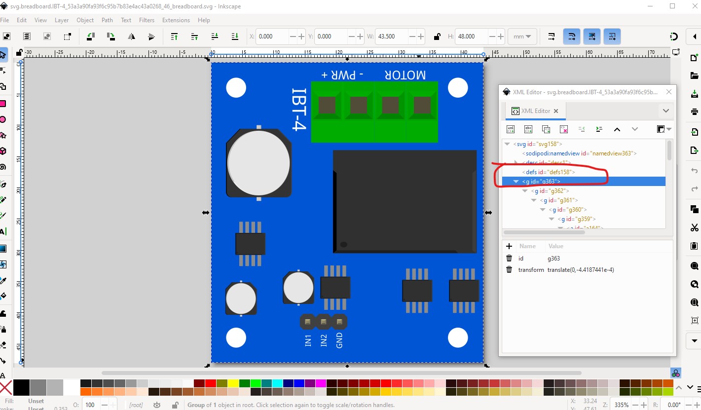
As well FritzingCheckPart.py indicates you are lacking a layerId in breadboard
Error 69: File
‘svg.breadboard.IBT-4_53a3a90fa93f6c95b7b83e4ac43a0268_46_breadboard.svg.bak’
At line 14
Found a drawing element before a layerId (or no layerId)
to fix that change the name of the group circled in red to “breadboard” from “g363”. This prevents your part from exporting as an image (the part will be blank in the exported image) which is annoying as people complain about it.
All this is covered in this tutorial on making parts.
Peter