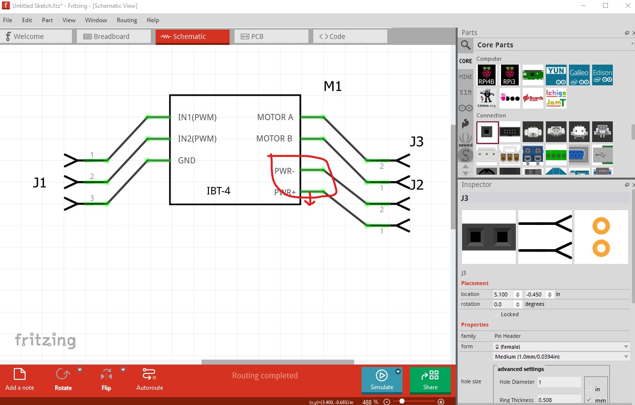
Not bad but a couple of errors. In schematic your pins are not aligned to the grid the bottom two on the screw terminals need to move down a bit so they line up with the grid. If you are using Inkscape Randy’s schematic extension makes creating correct schematics much easier.
the wire will connect to the center of the pin without a terminalId.
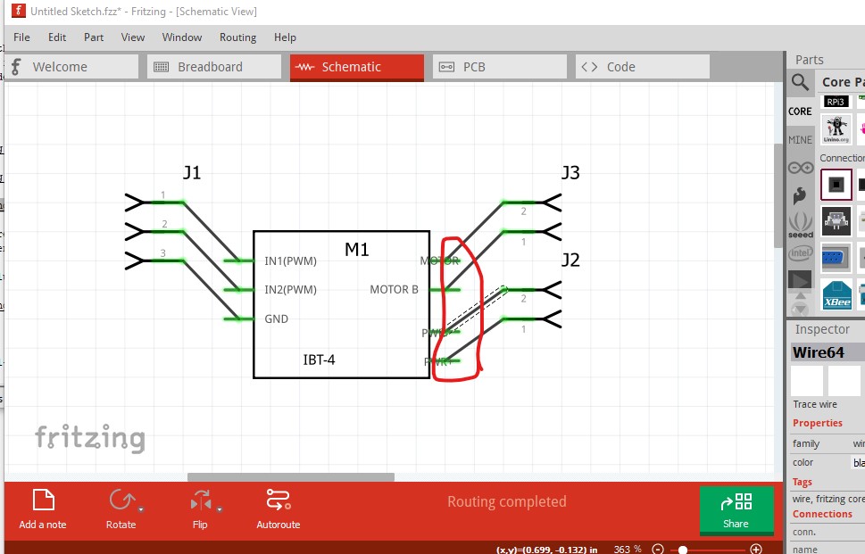
In pcb it would be preferable to suppress pcb view rather than have an error (the red rectangle indicates undefined pins.) That can be achieved like this:
replace this in the fzp file (you have to edit the file with a text editor, parts editor can’t do this)
which reuses the breadboard view as pcb (which won’t render in pcb) suppressing pcb view. Fritzing requires a renderer in pcb to function. As well your connectors need a terminalId (it isn’t deadly current versions of Fritzing insert them if they are missing) in schematic view (but not in pcb view as here)
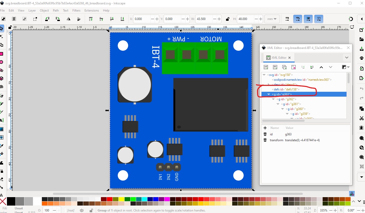
As well FritzingCheckPart.py indicates you are lacking a layerId in breadboard
Error 69: File
‘svg.breadboard.IBT-4_53a3a90fa93f6c95b7b83e4ac43a0268_46_breadboard.svg.bak’
At line 14
Found a drawing element before a layerId (or no layerId)
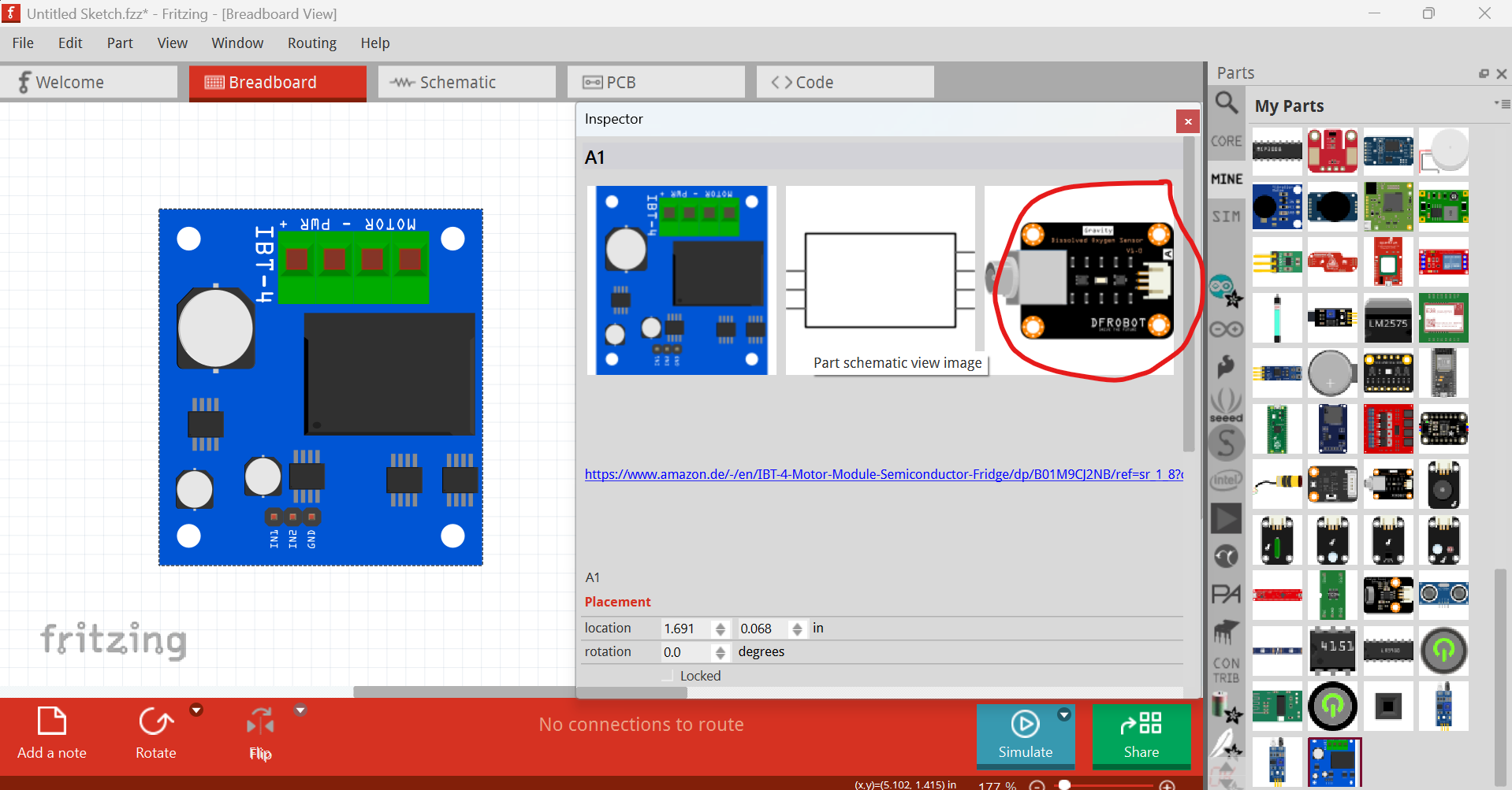
to fix that change the name of the group circled in red to “breadboard” from “g363”. This prevents your part from exporting as an image (the part will be blank in the exported image) which is annoying as people complain about it.
@jaby I assumed you have used the New Part Editor. Currently, the editor does not support missing connectors, and does not allow you to suppress the PDB view. As @vanepp mentioned, change the .fzp file.
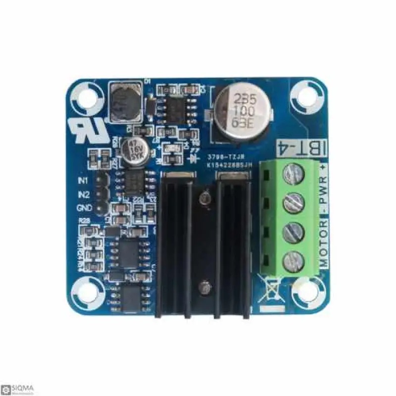
The IBT-4 motor driver (50A) is a solid choice for high-power applications, but pairing it with a reliable 10EDB40 Schottky diode can enhance efficiency by reducing voltage drops and improving heat dissipation. This can help protect your circuit from reverse currents. Have you considered adding one to your setup?
Note that I’ve suppressed the PCB view entirely (being lazy), so if you need PCB let Peter know (my zip archiver has been corrupting .fzpz files lately! I do know how to so though)
I had directly cloned an unrelated part (that has no PCB to make my life easier) with the new part editor so just ignore this
Actually the parts editor can do lots of things. It basically does automation work to edit the .fzp file. There are still downsides, like not being able to remove connectors in PCB view, schematic subparts, etc.