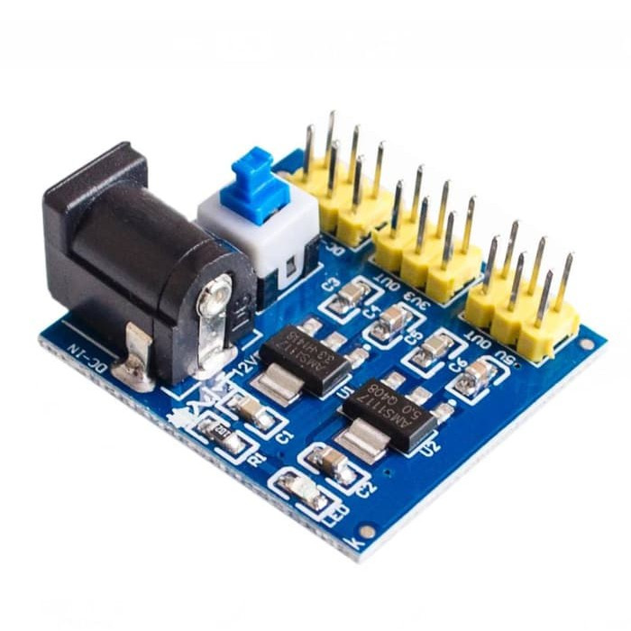
Welcome aboard! Given more information I could probably make such a part. To do so I would need a mechanical drawing or a pointer to the site that sells the board, to get the dimensions of the board and what the connectors do. A flat (as opposed to this one which is tilted) image of the board should be enough to figure out what is needed though since there probably isn’t a mechanical drawing.
edit:
I think the ywrobot (numberr 9 here)
http://omnigatherum.ca/wp/?p=262
is as close as you will come. It looks different but does the same thing i.e. provides 5V and 3.3V to header connectors for a breadboard.
Peter
Thank you so much Peter for your information
I made one myself, but it doesn’t seem to be perfect
电源转换模块.fzpz (51.5 KB)
Not bad, but indeed it has some problems. Schematic is broken:
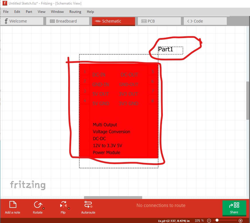
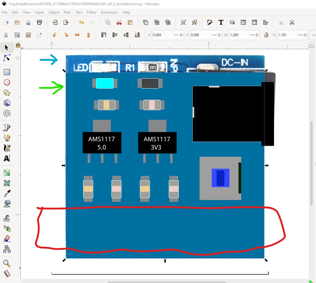
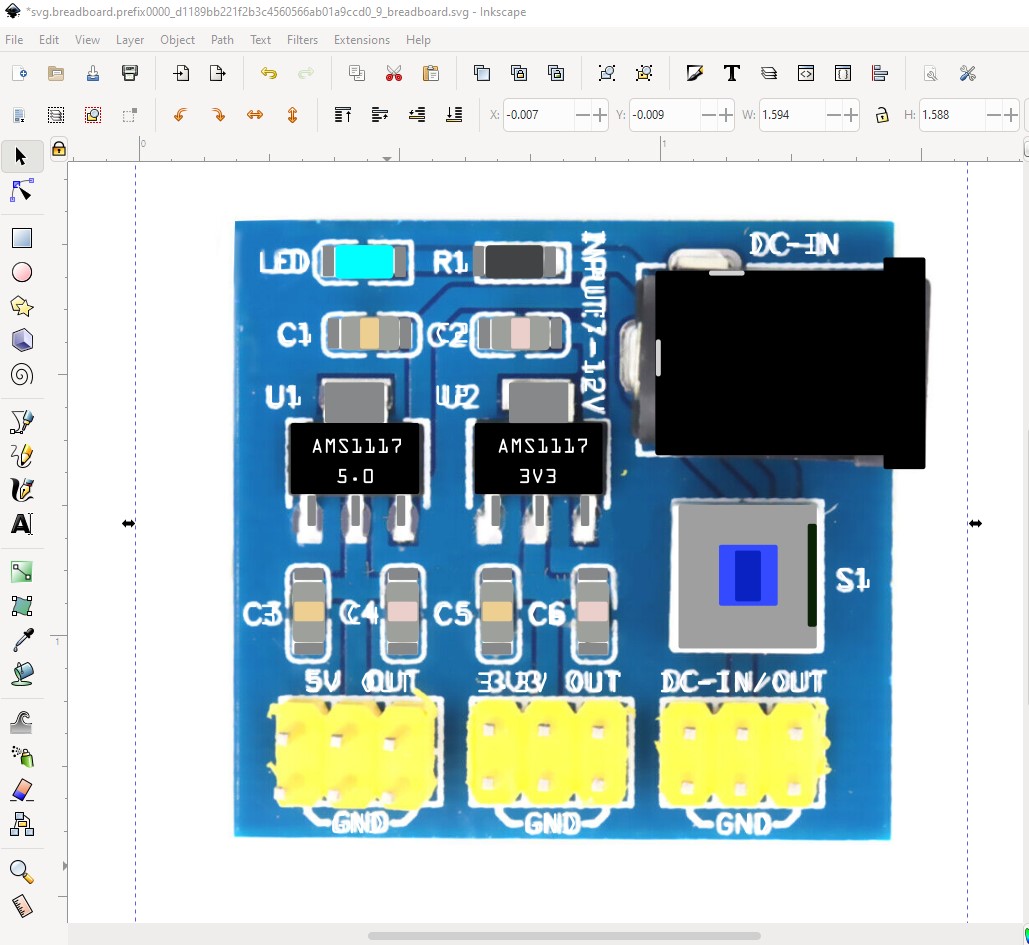
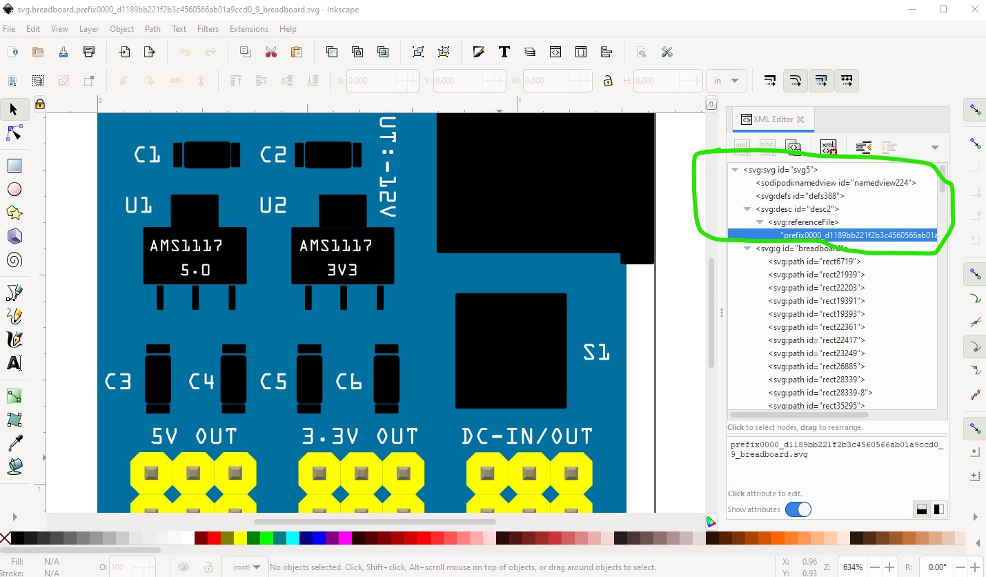
The part1 label indicates there is no label definition in the fzp file, the red rectangle indicates connectors not defined, which is indeed correct. There are 18 connectors in breadboard which all need defining in schematic (which only has 9 pins defined one lacking a proper label so it won’t work.) Pcb isn’t useful and should be suppressed. So lets start on breadboard. I grabbed a jpeg image of the board from a site selling them and imported it in to Inkscape. The site indicates that the pcb should be 30mm by 32mm so I scaled the image down until the board fit in to 30mm by 32mm. Then I changed the color of the background pcb to better match the color in the image. I also deleted the 0.1in header parts as I am going to replace them with a generic 0.1in 3 pin header later.
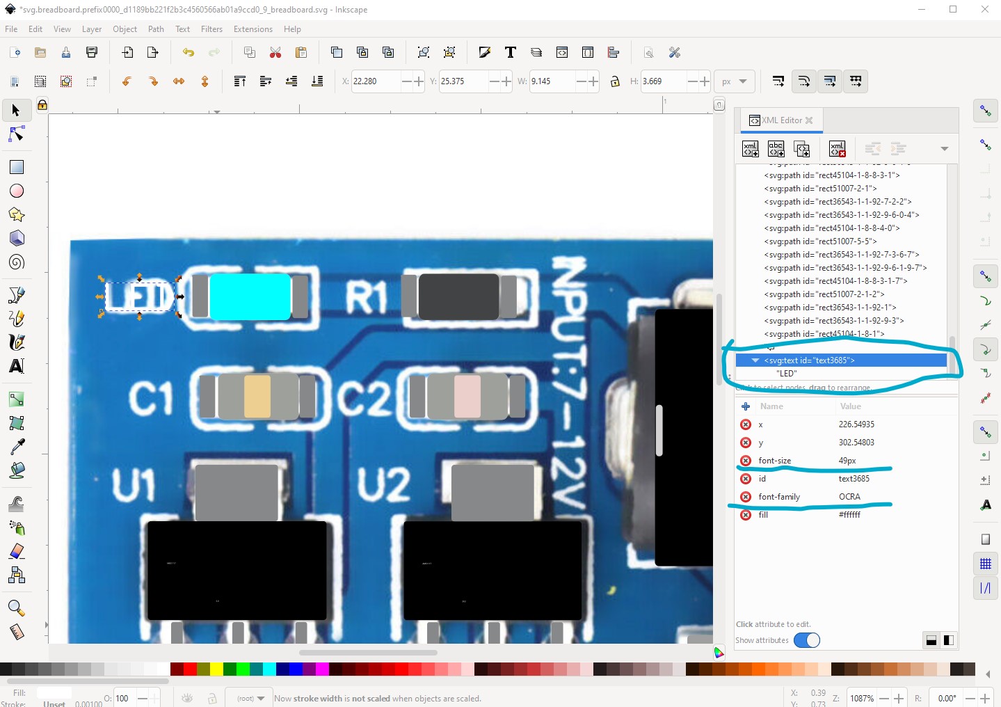
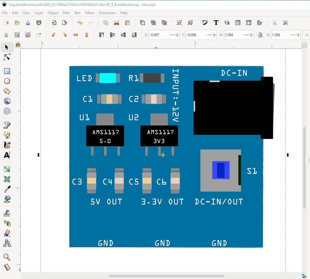
the current breadboard is importing fonts, which won’t work in Fritzing, Fritzing only accepts OCRA and DroidSans fonts and will substitute one or the other for other fonts. So I removed all the CSS (which Fritzing also doesn’t support) and the fonts from the svg and replaced all the text with OCRA text like this. Note here the background rectangle has been moved to the top of the svg so it is behind the jpg image so the parts in the svg are superimposed on the jpg image.
in this image all the text has been replaced with new text and positioned to the same general place as shown in the jpg.
here the jpg image is moved to the back so we see what the actual new breadboard will look like (without the headers!)
now I edited a generic male 3pin header created by the parts factory to change the color from brown to yellow by selecting the outline and changing its fill value.
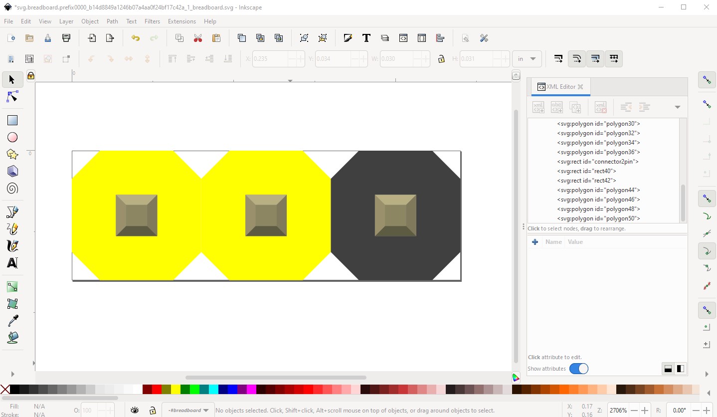
to do that select the outline path
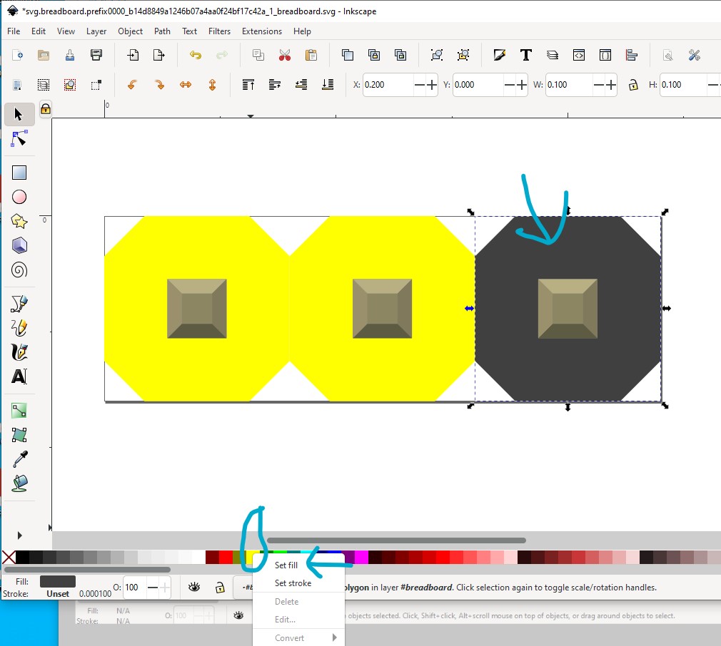
then set the fill to yellow then do an Edit->select all to select the entire part and copy it to the clip board.
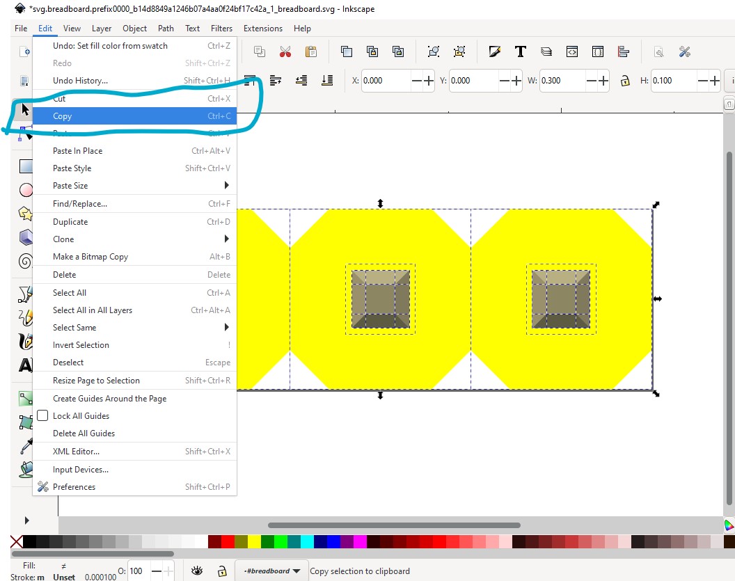
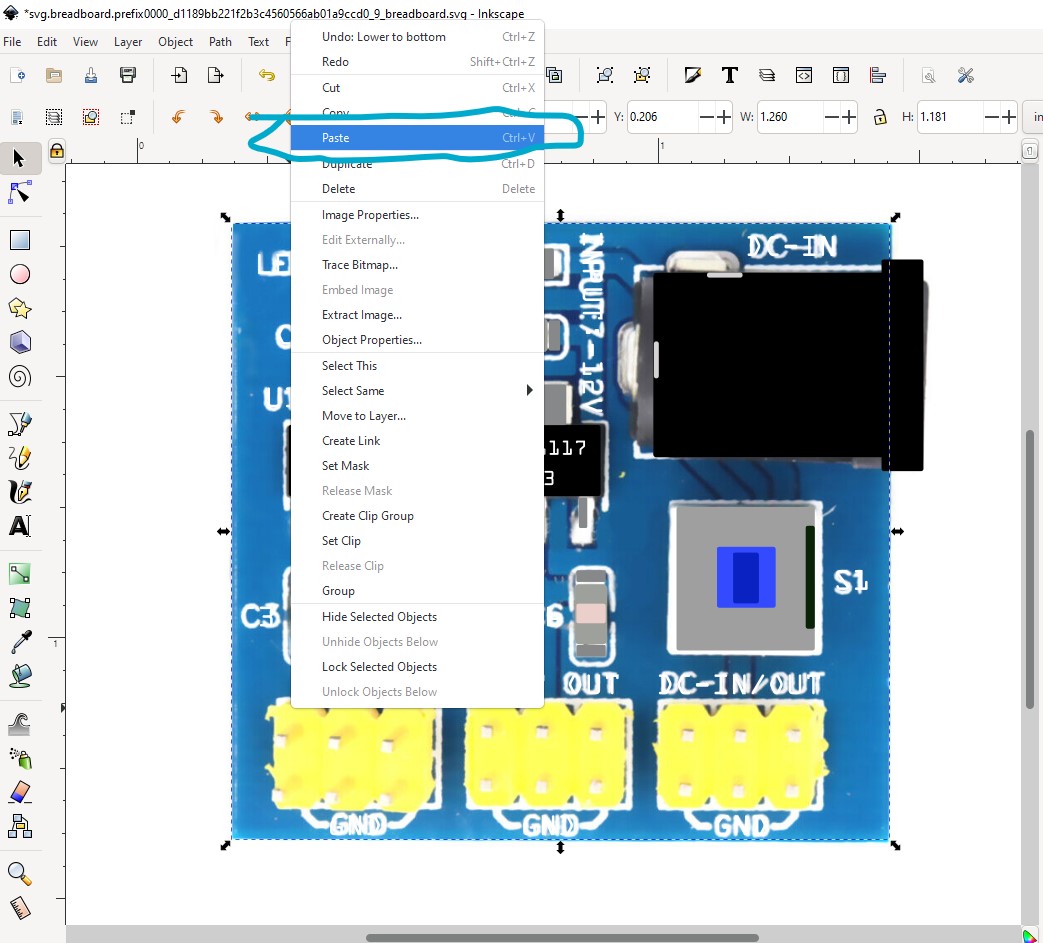
then paste it in to the breadboard svg.
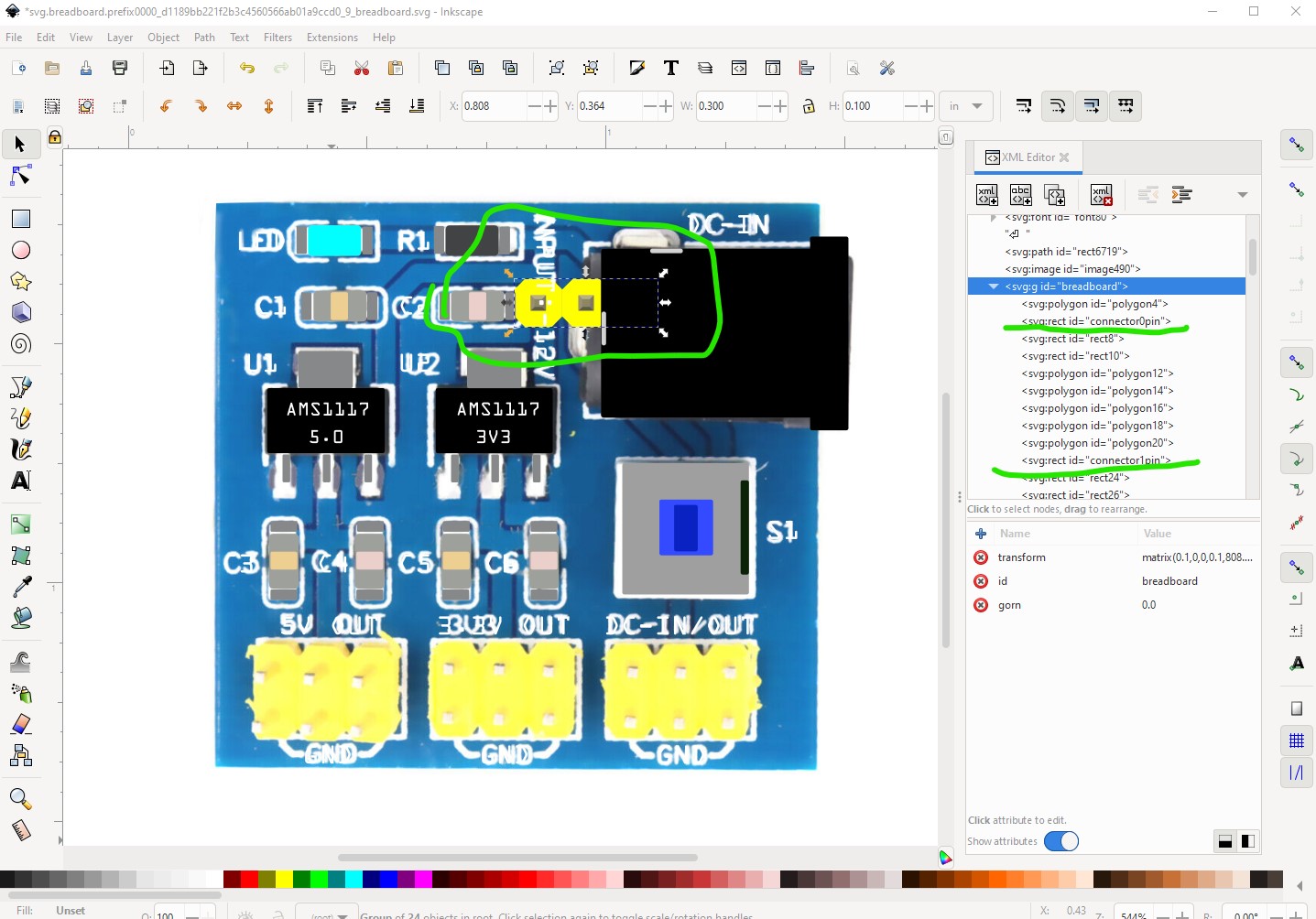
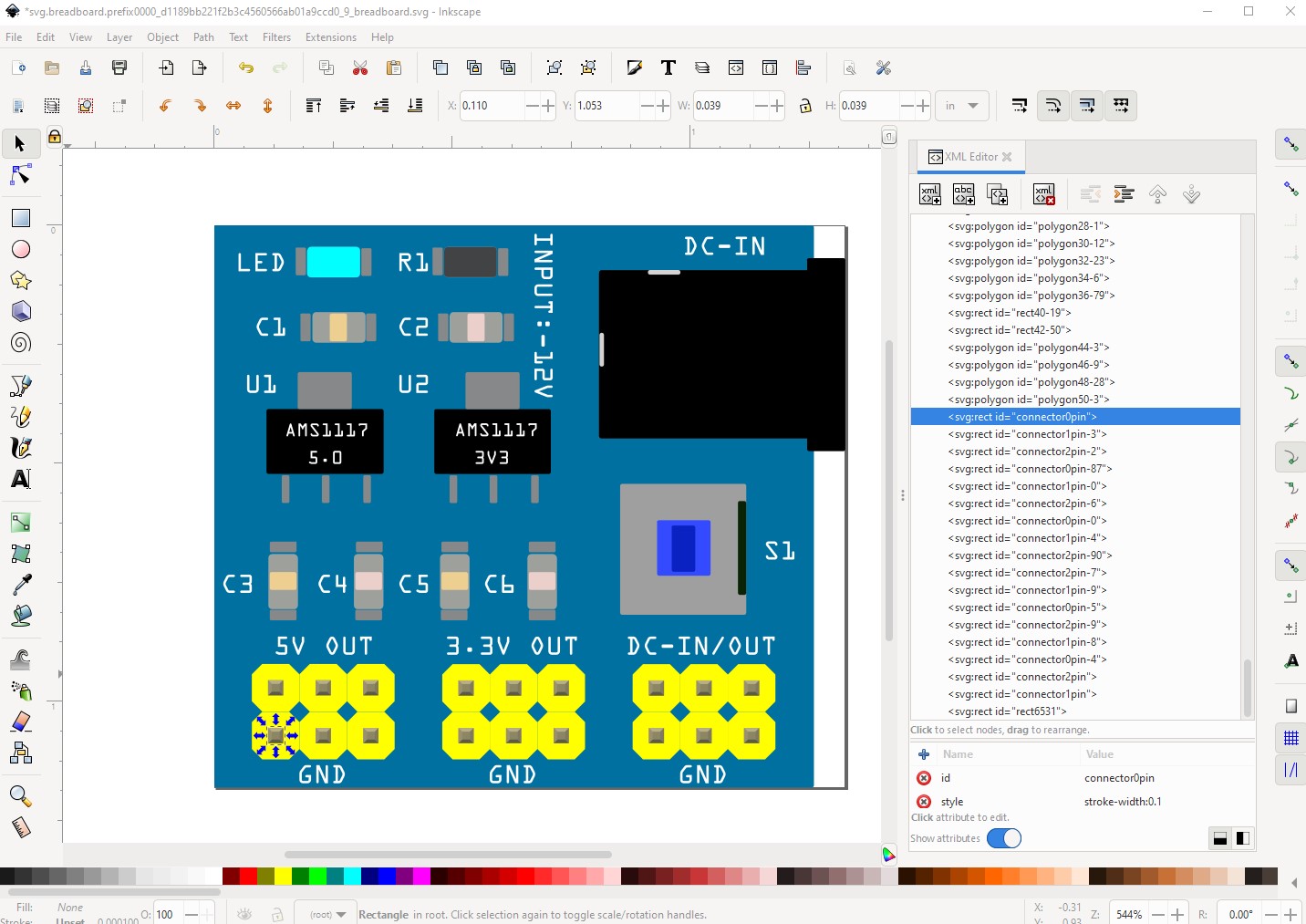
of note here is that the connector ids in the svg have been preserved across the copy paste. That is important because later we are going to want to change the position of the connectors and finding them without the labels is difficult!
here I have positioned the first header where it should go according to the jpg image and pasted in a second header below it.
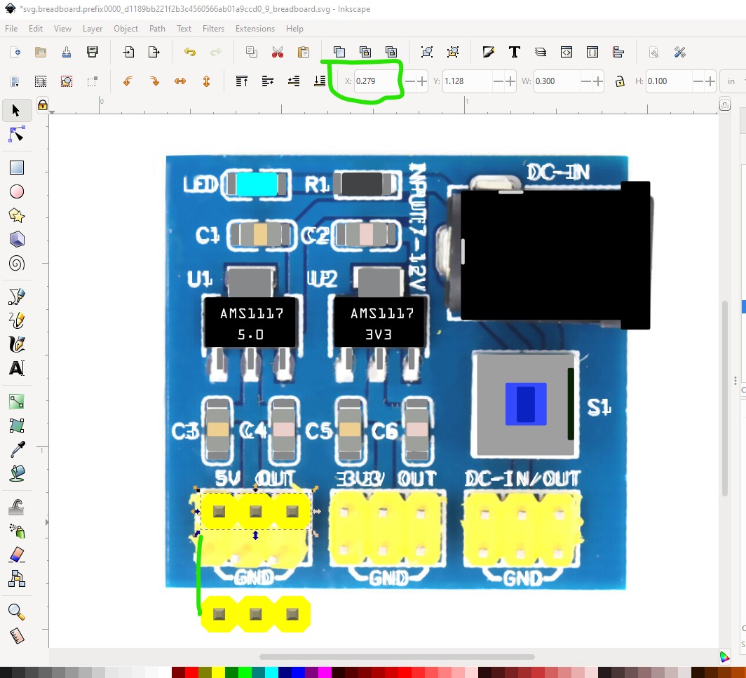
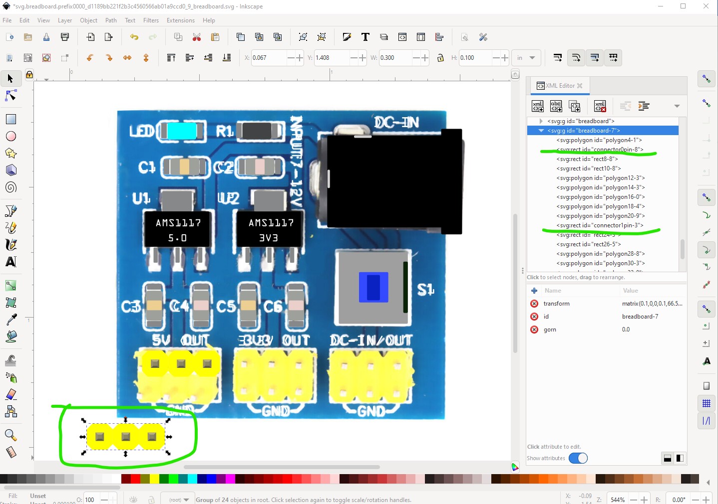
now use the x and y positions of the first header to move the second header to the same x coord and the y coord + 0.1in so the new header will be aligned on 0.1in boundaries below the first one.
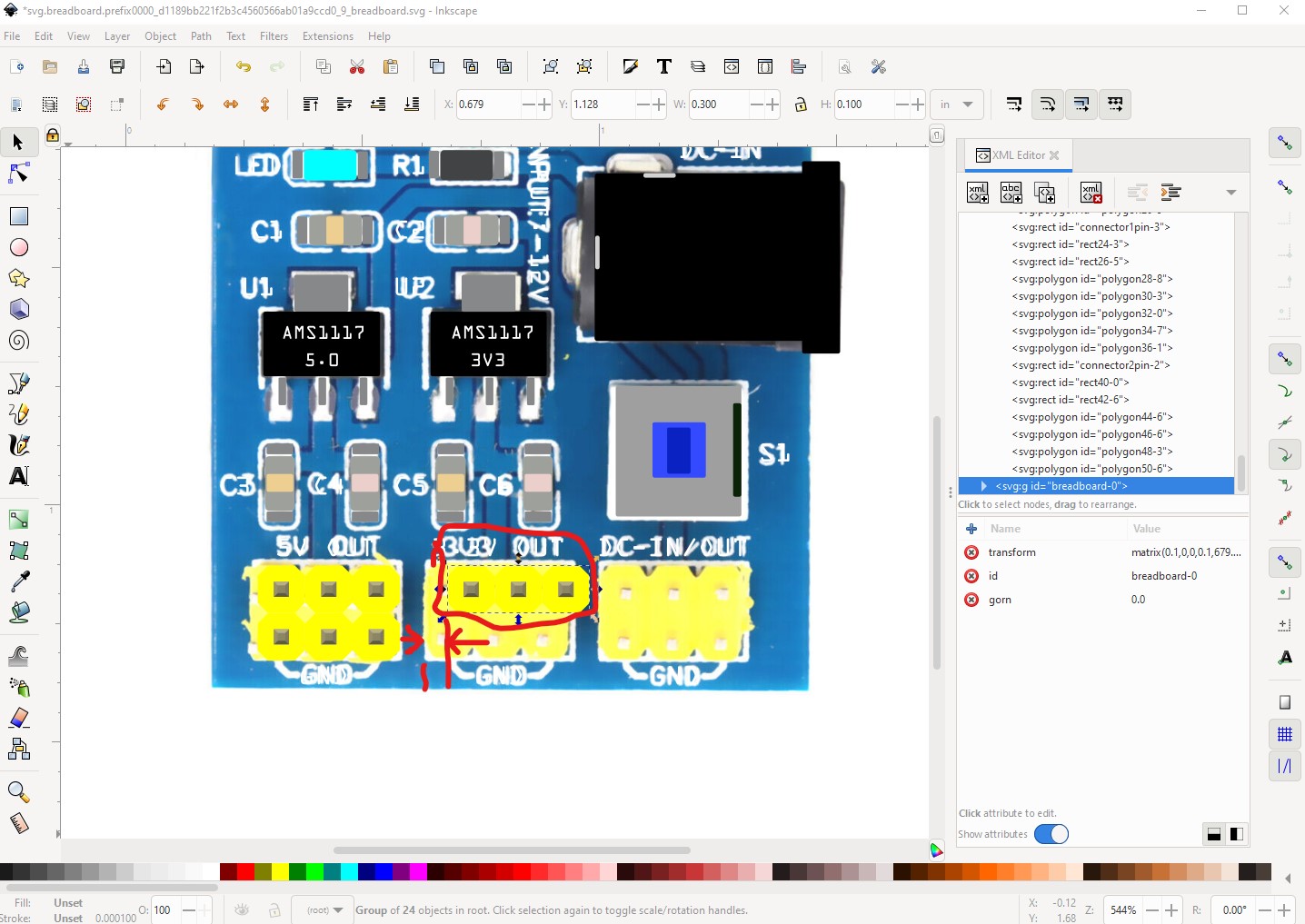
unfortunately aligning the second header on a 0.1in boundary makes it not match the position in the jpeg.
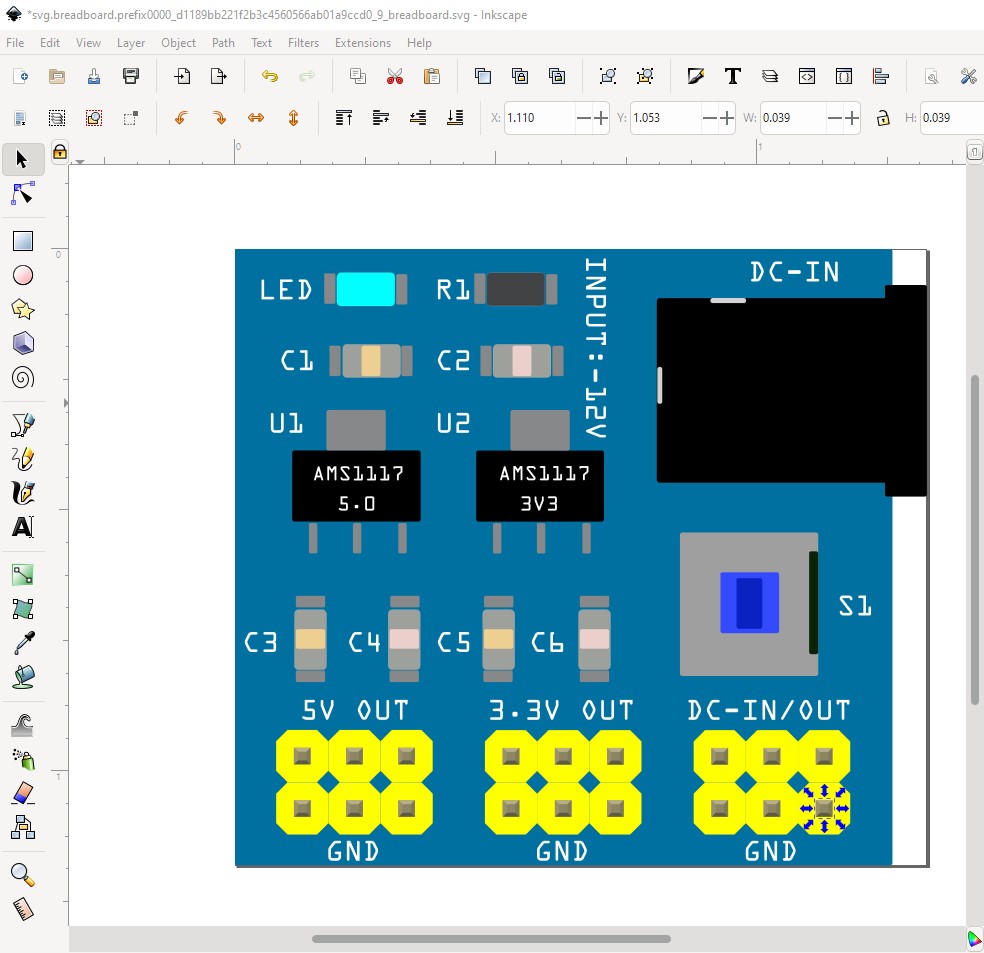
and the next is worse. I chose to center the pins in the pcb and leave them aligned to the 0.1in grid rather than matching the jpeg.
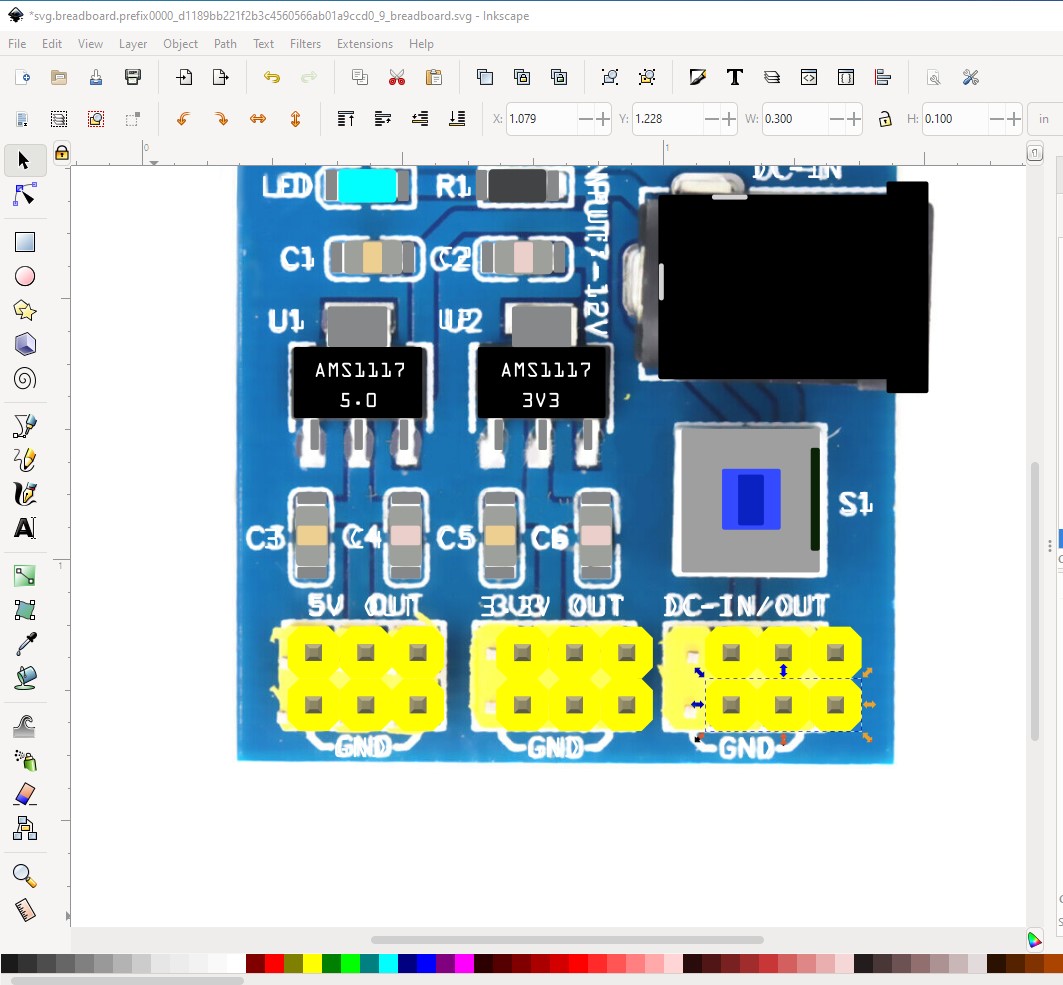
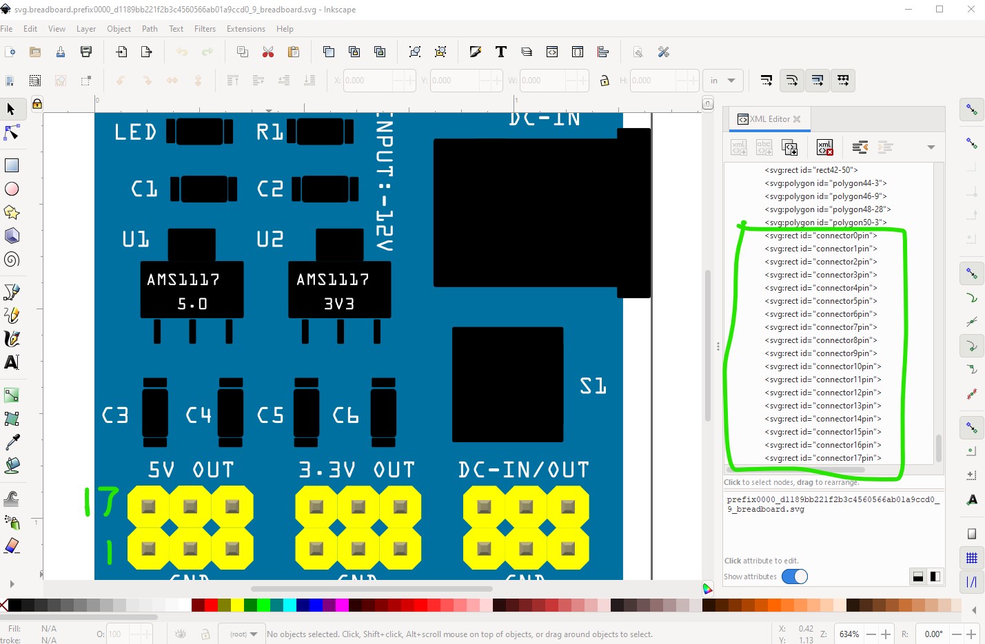
with all the connectors added it is time to position the connectors. I chose the bottom left to pin connector0 increasing across the bottom til connector8 (all gnd) then making connector9 the right side of the top row increasing to connector 17 like this
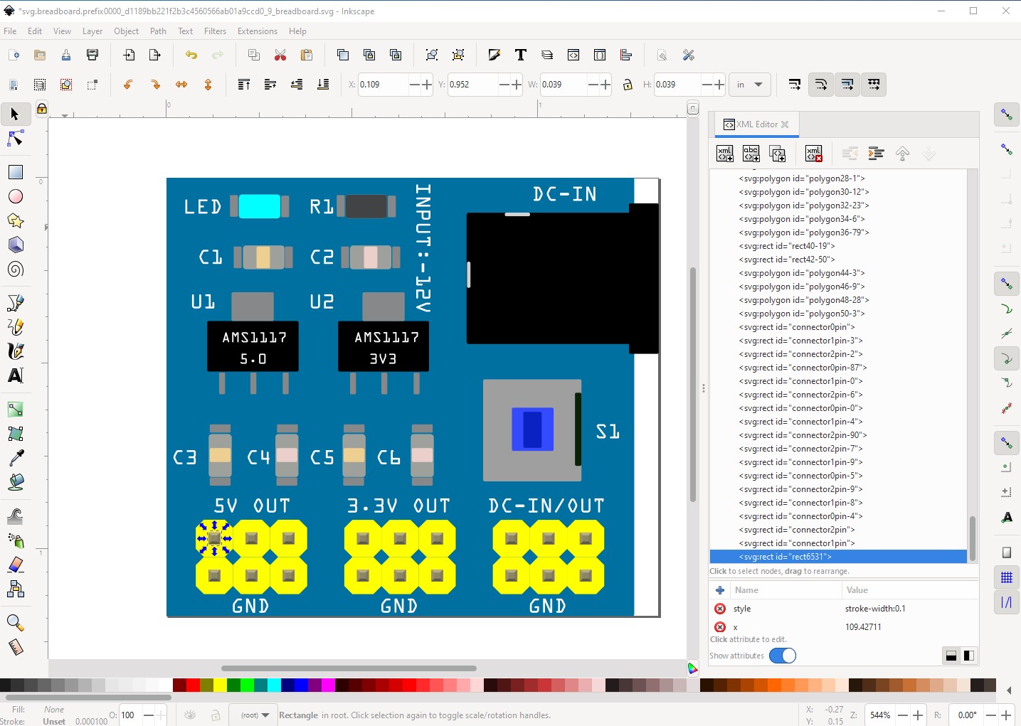
They are positioned at the bottom of svg so that a python script can renumber the pins automatically.
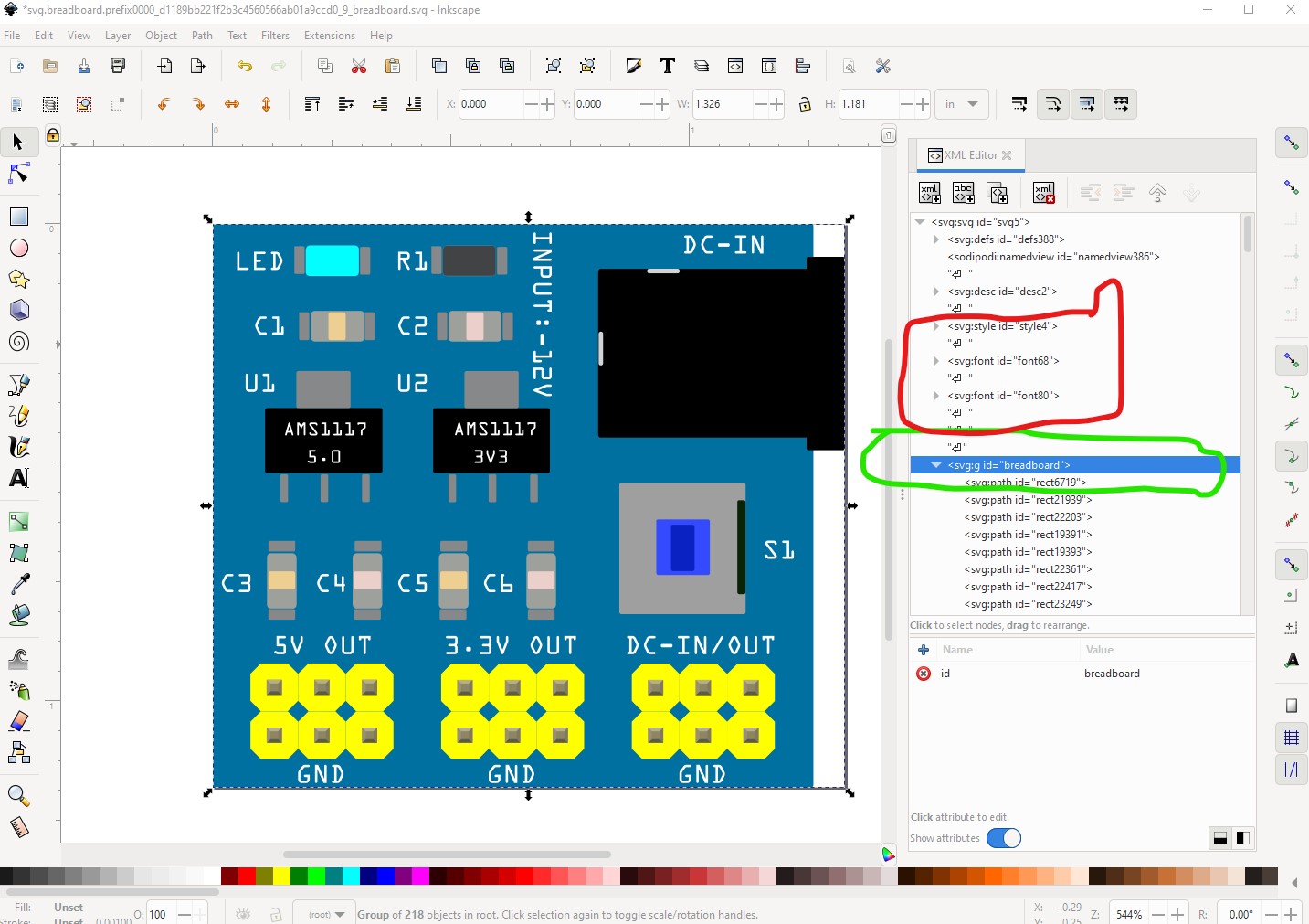
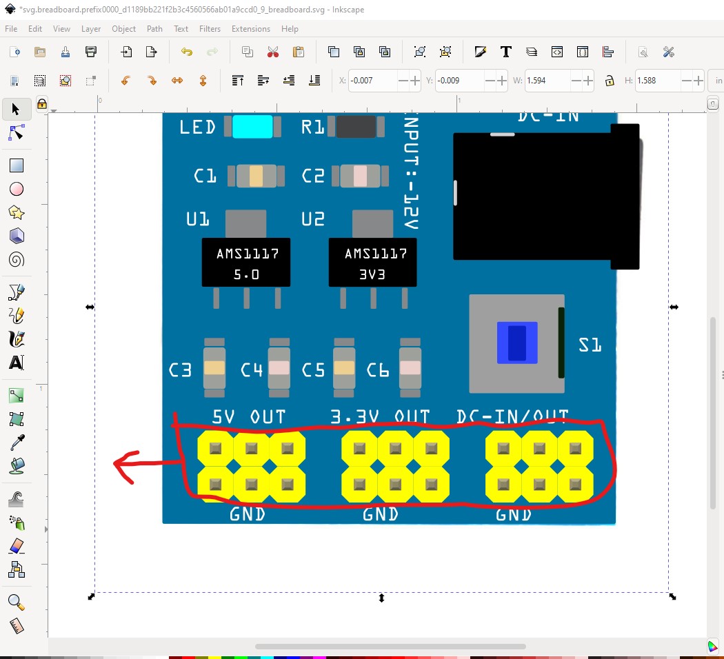
then I did an Edit->select all and Edit->resize page to selection to set the svg to start at 0 0 and reset the viewbox. I used a text editor to remove the definitions circled in red.
which leaves the completed breadboard svg ready to be saved and used.
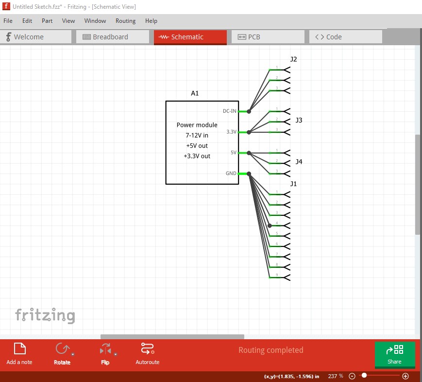
then I ran a python script to renumber the pins sequentially (you can also do this manually but it is more work!) Now on to schematic, as noted at the start schematic needs more connectors than it has so I used the Inkscape extension to make a new schematic with all 18 connectors. Which looks like this
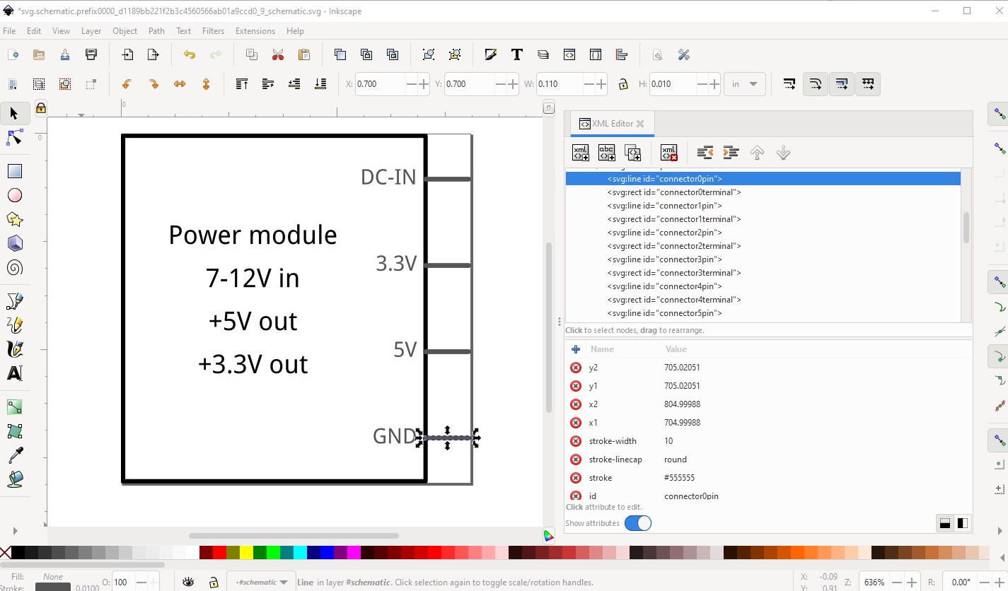
Here connectors0 to 8 (all ground) are all ovelaid on the gnd pin.
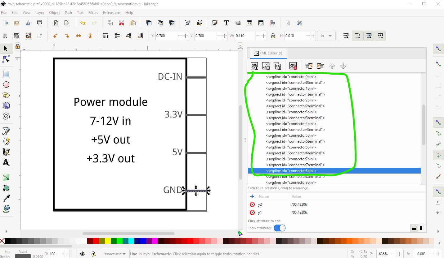
the same is true (but only 3 pins each) for the other 3 connections. Now I moved on to the .fzp file. I changed the file names and moduleId to make this a new part, added a label field and a more correct family name (the original will likely collide with the core part rtc file it was cloned from!) added a new description and reused the breadboard svg in the pcb definition to suppress pcb view (you can find instructions on doing so in this tutorial set)
Part creation howto part 1 breadboard and pcb
then I added the buses for ground (9pins) and each of the 3 output pins (3pins each) which were missing in the original fzp. That creates this part
power-module-12Vin-3v3-5vout.fzpz (8.4 KB)
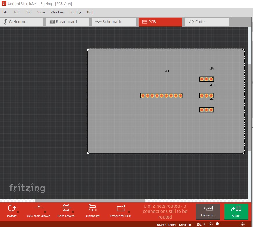
which looks like this in Fritzing
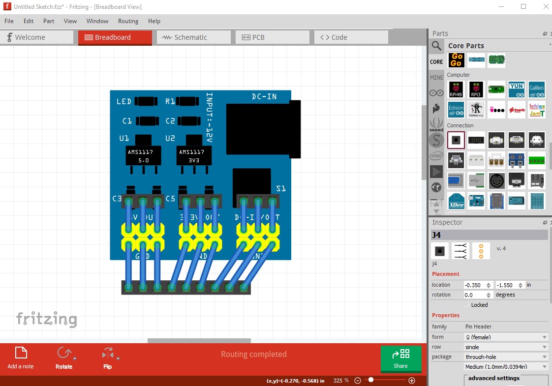
pcb has only the headers that connect to the power supply, the power supply itself is suppressed.
Hopefully this helps.
Peter