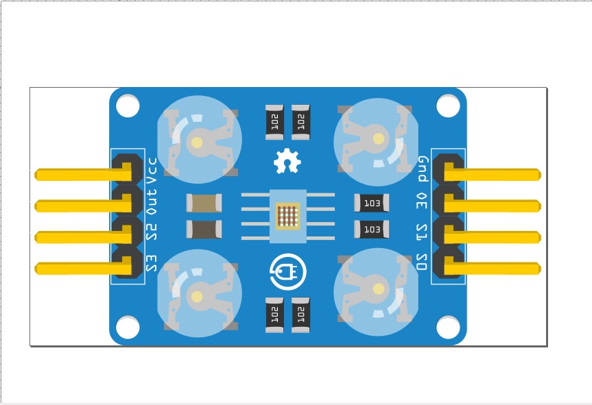
Hi all, I’d like to figure out how to edit this part I found online so the pins show sticking out of the top and bottom. The other problem is the pins don’t line up to the breadboard 100%. If you want to fix it cool if you want to point me in the right direction I’ll work on it. I intend to change the picture image with a clearer one for this TCS3200 color sensor
TCS3200.fzpz (933.5 KB)
You would likely be better to start from this part
If you download COLOR_RGB_Recognition_Sensor_TCS2300.fzz
in the temp parts bin you will find a better part for the tcs3200 (but still not right angle connectors.) Right click on the part in the parts bin and select export part to write a .fzpz file in the file system. Then unip the .fzpz file to get the .fzp file and the 4 vg files that make up the part. The right angle header is available here
although it is only three pins so you would need to modify it somewhat (which isn’t particularly easy!) This tutorial applies to current versions of Fritzing or I can make a part for you.
Peter
Thanks Peter you ROCK!
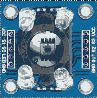
Before I get too far does your part look like this? The only one I see that has right angle connectors is a waveshare module which has all 8 pins on 1 side.
Peter
no my part looks like the one I uploaded LEFT SIDE top to bottom pins are VCC S1 S0 LED GND RIGHT SIDE top to bottom VCC S3 S2 OUT GND 5 pins on each side
1 Like