Custom Part
ESP32
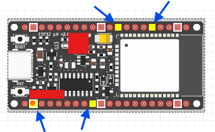
Need to know how to interconnect all the GND pins together in the following board. This is made with different ESP32 board and previous connections remains same as shown in yellow color. When clicked on one pin all other connected pins are glowing in yellow color. Need to remove previous connections and create new interconnection between GND pins.
vanepp
April 20, 2025, 5:57pm
2
Edit the bus connection in the .fzp file. Here is an example from one of my ESP32 boards:
...
    <connector id="connector14" type="male" name="Pin 15">
      <description>G</description>
      <views>
        <breadboardView>
          <p svgId="connector14pin" layer="breadboard"/>
        </breadboardView>
        <schematicView>
          <p svgId="connector14pin" layer="schematic" terminalId="connector14terminal"/>
        </schematicView>
        <pcbView>
          <p svgId="connector14pin" layer="copper0"/>
          <p svgId="connector14pin" layer="copper1"/>
        </pcbView>
      </views>
    </connector>
...
    <connector id="connector17" type="male" name="Pin 18">
      <description>G</description>
      <views>
        <breadboardView>
          <p svgId="connector17pin" layer="breadboard"/>
        </breadboardView>
        <schematicView>
          <p svgId="connector17pin" layer="schematic" terminalId="connector17terminal"/>
        </schematicView>
        <pcbView>
          <p svgId="connector17pin" layer="copper0"/>
          <p svgId="connector17pin" layer="copper1"/>
        </pcbView>
      </views>
...
    <connector id="connector31" type="male" name="Pin 32">
      <description>G</description>
      <views>
        <breadboardView>
          <p svgId="connector31pin" layer="breadboard"/>
        </breadboardView>
        <schematicView>
          <p svgId="connector31pin" layer="schematic" terminalId="connector31terminal"/>
        </schematicView>
        <pcbView>
          <p svgId="connector31pin" layer="copper0"/>
          <p svgId="connector31pin" layer="copper1"/>
        </pcbView>
      </views>
    </connector>
    <connector id="connector32" type="female" name="Pin 33">
      <description>J5-1</description>
      <views>
        <breadboardView>
          <p svgId="connector32pin" layer="breadboard"/>
        </breadboardView>
        <schematicView>
          <p svgId="connector32pin" layer="schematic" terminalId="connector32terminal"/>
        </schematicView>
      </views>
    </connector>
    <connector id="connector33" type="female" name="Pin 34">
      <description>J5-2</description>
      <views>
        <breadboardView>
          <p svgId="connector33pin" layer="breadboard"/>
        </breadboardView>
        <schematicView>
          <p svgId="connector33pin" layer="schematic" terminalId="connector33terminal"/>
        </schematicView>
      </views>
    </connector>
  </connectors>
  <buses>
    <bus id="GND">
      <nodeMember connectorId="connector14"/>
      <nodeMember connectorId="connector17"/>
      <nodeMember connectorId="connector31"/>
    </bus>
  </buses>
basically you need to change the “connectorId=” connector numbers to match the new connector numbers for your part in the buses section of the .fzp file for the part.
assuming you are using parts editor (which I don’t recommend and don’t normally do!) this should work
In the editor under the list of pins on the right there is a check box that says set internal connections. Once that is checked it will show the internal connections as ratsnest lines which you can then right click on and select delete connection.
This tutorial may help you with all of this:
Someone in this forum post
requested help to fix up a part. So while doing that I decided to record what I needed to do in order to fix the part to provide a tutorial to create new / fix broken parts. If you start from the Tarjeta S4A EDU.fzpz file posted in the above thread, you should be able to recreate my improved part posted in the same thread. I started by loading the original part in to Fritzing, that indicates breadboard is (at first look anyway) pretty good, but schematic and pcb are…
Peter
vanepp:
set internal connections
Thank you verymuch for your quick reply. I have solved the issue using “set internal connections” option