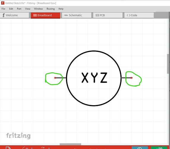
The image needs to be a svg file not a png. It also needs to be a specific format (described here)
A part made from the above image looks like this
mystery-part.fzpz (3.4 KB)
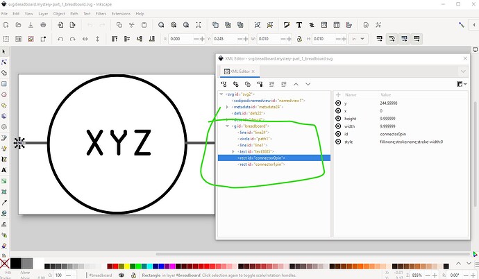
unzip the .fzpz file to get the fzp file and the 3 svg files for the part. Breadboard needs to look like this (with the layerId set to breadboard which needs to match the .fzp file in order for the part to export as an image.) The connectors need to start at connector0pin (and again match the definition in the fzp file) and in this case be on the end of the pin so the wire connects to the end of the pin rather than the middle of the pin. The entire part looks like this (here displayed in Inkscape)
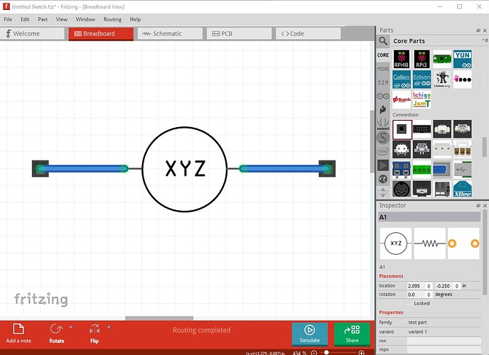
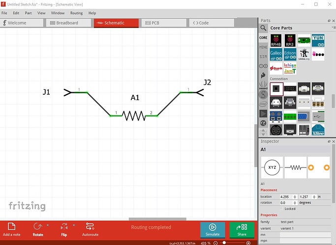
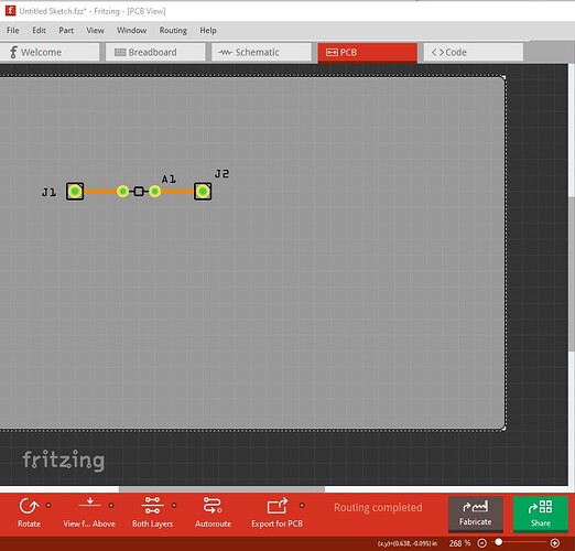
The part looks like this
breadboard
schematic
pcb
breadboard with no connections indicating where the connect point is
here I didn’t choose to use a terminalId (which would have made the entire pin red but still connected to the end of the pin because of the terminalId.)
Peter
