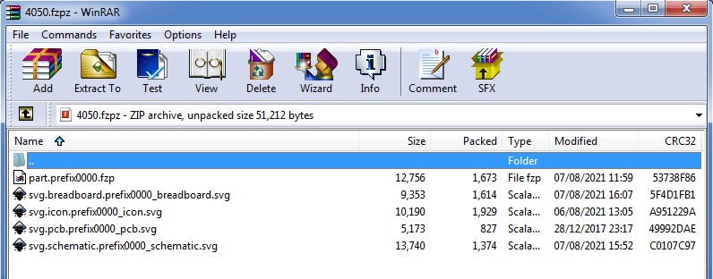
I’ve created my new part using a couple of other parts as a template. I noticed that all the parts that people share have very long file names. The files in the .fzpz are in the format;
svg.schematic.prefix0000_XXX_schematic.svg
Where does the XXX code come from and is it necessary?
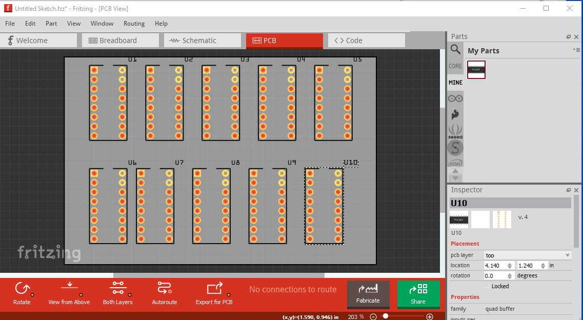
These are the files of my new part, do I post like this?
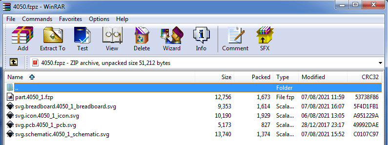
The file name comes from the parts editor and is long (and partially time based) to be unique as all parts need to have unique file names both in core parts and user added parts and this is an easy way to do that for user supplied parts. If you are careful to make sure the file names you are using (both the fzp and svg files) are not in core parts you can use short versions in the file name. I usually use the name of the part such as 74x125 so svg.schematic.74x125_1_schematic.svg . The _1 on the tail end is a version number, so if there is an error found in the part that changes to _2, the svg.schematic.74x125_1_schematic.svg changes to svg.schematic.74x125_2_schematic.svg to be unique from the first version and (if this is core parts) the original part file is moved to the obsolete directory, so old sketches will still work from the original part in the obsolete directory, but will tell you there is a new part available and ask if you want to upgrade. In this case I would go with part.4050_1.fzp for instance (and the same for the 4 svgs.) As there isn’t one in core parts at present:
There is a chance if you do this that someone else will have a same named part and you won’t be able to load the two of them together at the same time but the chance of that is usually pretty slim.
No, you zip (I use 7zip but any zip program should work) the 5 files in to an archive and name the archive 4050.fzpz and post the fzpz file. Fritzing will load the file, unzip it and install the files in to the mine parts bin from there. That means you can modify parts by unzipping the .fzpz file to get the source files that make up the part. The svg.schematic.filename_1_schematic.svg is loaded in the fritzing parts bin in part repository format which is core/ for the fzp file and svg/core/schematic/schematic.svg (and the same in 3 other directories) for pcb icon and breadboard. This is the format needed to submit a part to the core parts repository on github as well. There is currently nothing I know of that converts between the two formats but I intend to add that to FritzingCheckPart at some point (not done yet though.)
In addition to the “fixed” requirement that all of the names be unique, there is a “suggestion” that names be meaningful. See the information under “4. File Naming Conventions” on the graphics standards documentation page.
Note: That document is describing the file names for the core parts. That can apply to the files in the fzpz files as well, but those “ALSO” need to have the specific prefixes:
part.xxx.fzp
svg.breadboard.xxx.svg
svg.icon.xxx.svg
svg.pcb.xxx.svg
svg.schematic.xxx.svg
Those correspond (roughly) to the folders that the files are stored in, and where they would be if they were to included in the core library
fritzing-parts/core/xxx.fzp
fritzing-parts/svg/core/breadboard/xxx.svg
fritzing-parts/svg/core/icon/xxx.svg
fritzing-parts/svg/core/pcb/xxx.svg
fritzing-parts/svg/core/schematic/xxx.svg
If one or more of the svg files for your part are (can be) exactly the same as one of the svg files in the core parts library, the svg can be left out of the fzpz file. If the name for the view file in the fzp file is not in the fzpz part file, Fritzing will look for it in the core parts folders. This can be useful for parts that for example have a standard PCB footprint. Or where the breadboard and schematic view do not change, but a different pad size or shape is wanted for the pcb view. Only the changed view svgs need to be included in the fzpz part. With a unique name to not conflict with core parts.
The technical requirements for converting is straight forward. remove (or add) the part. and svg.«view». prefixes from the files, and move them to the the right folders. Remove or add any guid in the file names. Only the guid needs a matching change in the fzp file. Probably generate a new module id in the fzp. That should be enough for a batch conversion. For interactive, prompting for names that match the naming conventions would be good, and checking that the result does not conflict with existing core parts.
Thank you.
The files I showed in the screendump were already zipped (if you look at the filename at the top). I had WinRar already installed, so I’ve been using that. I’ve modified the file names as suggested;
The pcb svg is just a standard 16pin dip, but if I delete it as I think microMerlin suggests, then the part fails to load, with missing file error. Do I need to change the .fzp file to point to the core, if so, how? This is how it is now;
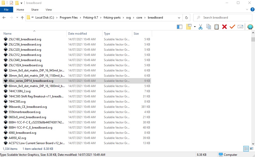
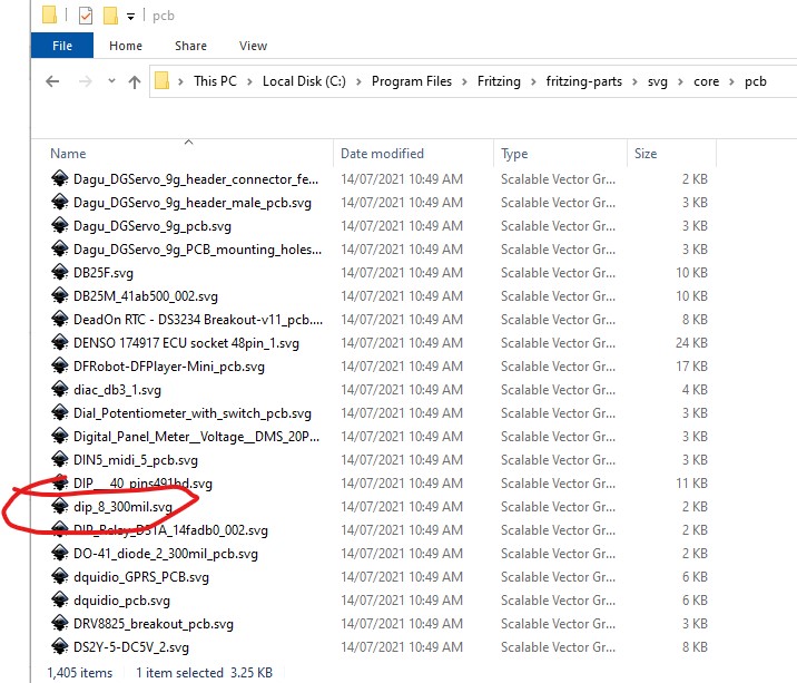
Yes, it needs a name in the fzp file that points to an existing name in the core parts repo for this to work and there isn’t a 4050_1.svg file in core. As far as I can see there are no suitable names (there are odd ones like 74HC139N_2.svg which appears to be 16 DIP (but because of the name, a bad choice in my view!) @microMerlin only discovered this works in the last year or so, I had not been aware that it worked, so have never used it, and it doesn’t look like anyone else had either. The desired case would be a dip_16_300mil.svg like the dip_8_300mil.svg that is there now but at present there isn’t one. The pcb file name in your svg would be svg.pcb.dip_16_300mil.svg which, when not found in the current directory would be looked for in core parts’s pcb directory.
there is one in Sparkfun parts: sparkfun-digitalic_dil16_pcb.svg but it is in an old format (separate copper1 and copper0) with pad as the pin definitions in the svg which likely won’t match the pin designation in your fzp file and the separate layers will be a problem. So for now I’d go with the same as everyone else and have a redundant standard 16pin pcb file named svg.pcb.4050_1_pcb.svg until we get around to fixing core parts (it is on my list now I know it can be done!)
The dip_«pins»_300mil.svg files are from of the factory svg part files. It works without the file actually being in the core parts folder. I just tested it by creating a 16 pin dip generic part, saving as new part, exporting, unzipping, deleting the pcb svg, changing the fzp entry to
<layers image="pcb/dip_16_300mil_pcb.svg">
and making the module id unique by incrementing the final digit, and rezipping. It loaded fine.
However (as I recall) I think that only works if the family is “Generic IC” so it thinks it is a generic IC and the downside is that it will happily rewrite your part from inspector with unpredictable results if you change things (number of pins, pin labels, width) in inspector all of which are undesirable in a specific part. If you change the family to 4050 as I think you should. this won’t work any more. I think we want specific defined footprints for cases like this (and even more for the various SMD outlines!) that are not a part of parts factory.
If true, and it can’t be fixed in the code, we may want to add the generic factory footprints to the core. Then it would not care about the family. Somewhat Defeats purpose of factory though.
We’ll see it when up load, but was the family in the fzp file set to 'Generic IC' ?
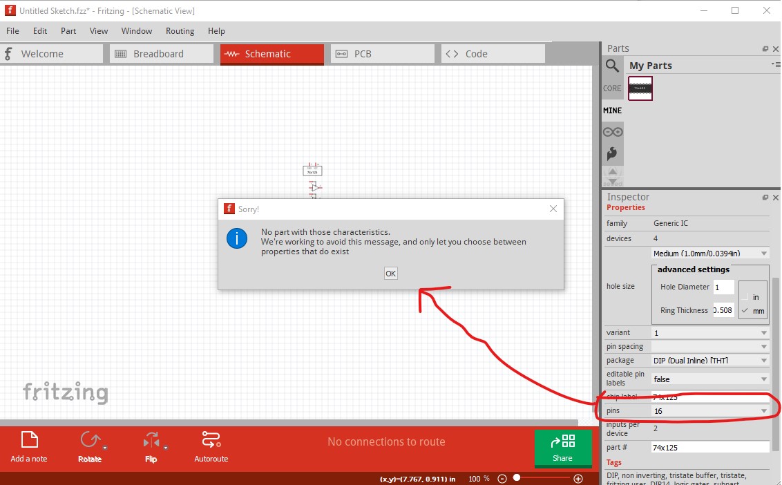
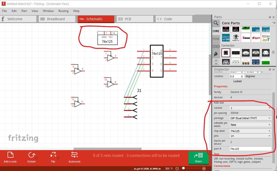
It is possible this may partly work. Here I modified a test copy of my 74x125 part (which has schematic subparts as does OPs new part, based on this one) with the family changed back to Generic IC from quad buffer and the pcb layer set to layers image=“pcb/dip_14_300mil_pcb.svg” as expected it loads correctly initially and trying to change the pins from 14 to 16 in Inspector gets this error message:
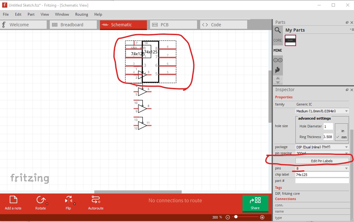
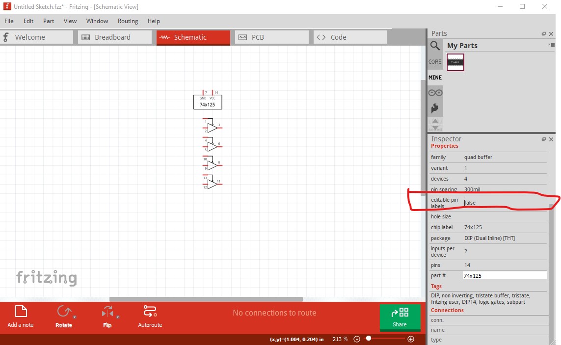
and leaves the package at 14 pins. So far so good. But now I changed edit pin labels false to edit pin labels true and the expected problem shows up (and an unexpected one too!):
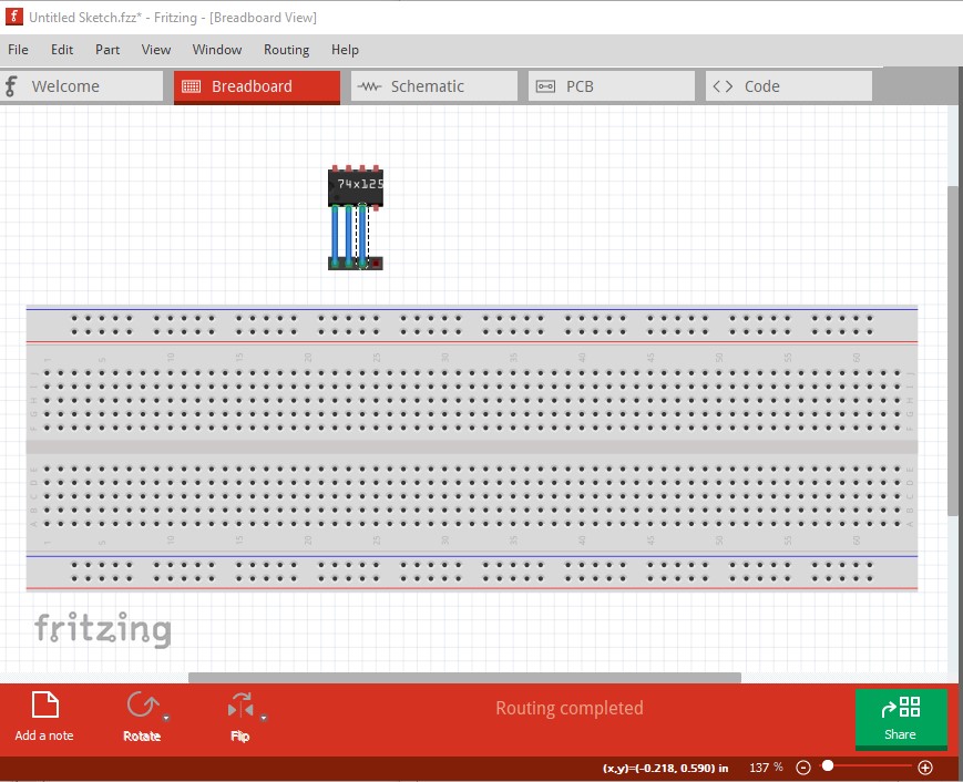
I expected to get the box with 14pins and labels, but instead get a 8pin box with labels. I expected this to break the subparts but I can move the subparts in the original chip around still as well as the new 8 pin part in schematic but I expect the sketch is now screwed up as it has a new unknown entity in it in the form of the 8pin part in schematic. Indeed it has screwed up breadboard (which used to be a 14 pin DIP):
I think this won’t be a problem when I set the family back to quad buffer:
property name=“family”>quad buffer
leave the pcb layerId
layers image=“pcb/dip_14_300mil_pcb.svg”
and copy my original pcb file in to core parts dip_14_300mil_pcb.svg so it exists there (this shouldn’t bother the parts factory because it doesn’t generate its pcb files in the parts repository but in a temp directory.)
I lost track in that. What happened if you did NOT use family of Generic IC, and did not have an actual pcb svg file in either the core pcb folder or the fzpz? Just specifying pcb/dip_14_300mil_pcb.svg in the fzp with no real files matching?
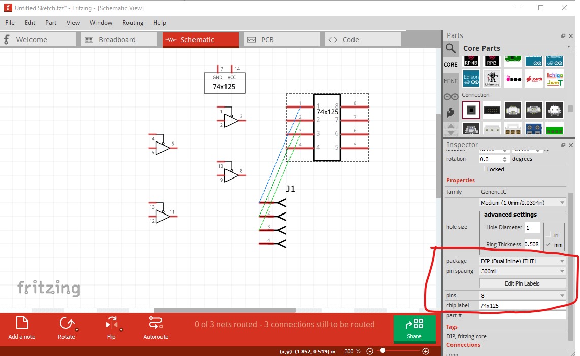
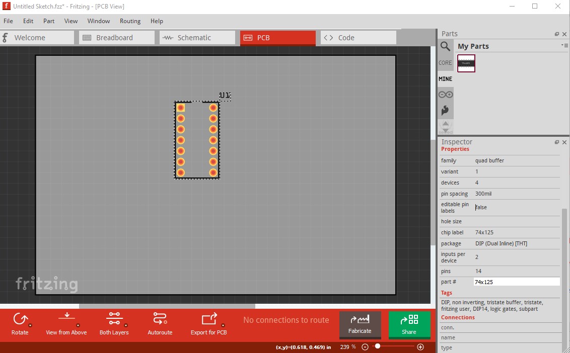
I didn’t actually try that til just now, but that too seems to work although I don’t know how (perhaps the swapping mechanism finding a match in parts factory somehow?) Here there is no pcb svg in the fzpz file and no dip_14_300mil_pcb.svg in core parts, yet it finds an appropriate footprint.
That is one of the “magic” file names that Fritzing recognizes. So this was not actually a good test of leaving a file out of the fzpz, to pick up the one already in core.
I asked about a list of those magic names a while ago, but never got a response. Have to dig through the code. Another item that FritzingCheckPart will not currently handle. You need a way to get factory to generate the file for you when testing. Or at least recognize it as a magic name, and not complain that it does not exist.
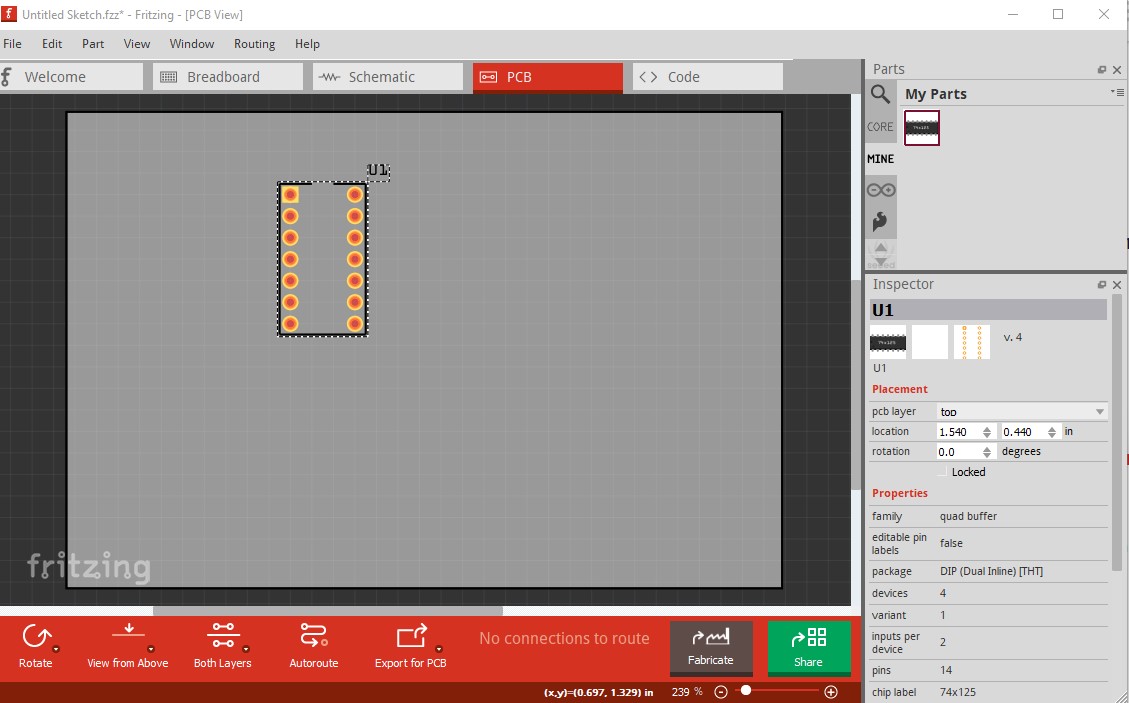
I’ve noticed that the “pcb/dip_14_300mil_pcb.svg” places a 14pin IC socket vertically, while the “pcb/dip_16_300mil_pcb.svg” places the 16pin socket sideways. It seems odd that there is this inconsistency in the factory svg parts library.
I would prefer my pcb sockets vertical, so I’m not sure whether to include the pcb.svg file in the fzpz. I know I can rotate it after inserting, but then I have to rotate the label back and it’s a hassle. I have lots of IC’s to insert and it’s just an unnecessary waste of time.
Another question: How do I control the placement of the label in pcb view? It places the “U” label off to the side, but I would prefer it central. I can’t see anything in the fzp, is it hardwired in?
It actually depends on what view you drag the part in to (there is a bug report about this open on github)
I think the rpc calls that create the other views are missing a parameter because it is consistent in the view that you drag in to but not (usually) the other two views.
Dragging them in to PCB should always align them right but then schematic and breadboard will be off in random order until the bug is fixed (and there isn’t currently a milestone for a fix!)
As far as I know it is hardwired although there may be an undocumented fzp attribute I don’t know of. It may be worth making an enhancement request (that used to be fairly futile, because development had died, but development has restarted and though bug fixing has priority some enhancements especially if they are easy, are being done)
Odd! For me both work correctly on both 0.9.6 and 0.9.7 under Win10. Here I modified my 74x125 test part and changed the dip_14 (which always comes out vertical) to dip_16 and it also always (at least in 10 tries) comes out vertical.
That may not be so easy , as I recall they are generally made with a sprintf from a parameter list which makes finding all the possible values exciting.
Or generate a complete set of svgs for all possible sizes and pitches (which will be a pain to maintain.) Yet another item for the todo list for checkpart … I’ll have to find a different svg (that isn’t a special file name) to see if it will search core for a missing svg.
edit: it still works. I replaced the dip_16_300 in the test part with layers image="pcb/74HC139N_2.svg which is a 16pin dip svg in core parts and it still finds the footprint fine.
Yes, very odd! The placement is perfect for me except for the orientation.
I’m on 0.9.6 as I found 0.9.7 had a massive bug that prevented me from changing the number of pins on the generic IC. I’m running it on my laptop on Windows 7. My desktop is down at the moment.
As @vanepp said, the default position is built into the code someplace, and there is nothing currently that can be done in either a specific part, or in user configuration to change that. The label can be moved after the part has been placed. I have never worried about it, since I seldom have a specific location that I always want the label to show up. Though for some parts (resistors), central is the normal choice for PCB view. My process when adding a part is to immediately set a few things like that.
A note though, when using multiple copies of a part. If you cleanup things after placing the first part, duplicates of that part will keep the relative position and orientation.
That is more consistent than my experience. What memory says, is that placement (in the initial view) is consistent for a session. For a specific part, whatever orientation the first placement gets will be the same for all future placements. However, shutdown Fritzing, and restart, and the next placement of the part might have a different orientation. I have never formally checked and recorded cases and steps to get there. That is just my casual observation. My process is to (automatically) rotate the part, rotate and possition the label when I place the first instance, then use duplicate from there on to keep consistency.
I have a script that generates permutation based on lists of possible values. It should not be difficult, if I can find that sprintf, and deduce the source/possible values for the parameters