As far as I know they are all based on my original DM860A part which as noted (and just corrected in this post)
has a bug which I just corrected. That will solve some of your problem with the can’t find this part error and the motor driver being missing from your sketch. For the limit switches if you would upload the .fzpz file for both the NO and NC versions of the switch (upload is 7th icon from the left in the reply menu) I can probably tell you why they won’t load together (probably duplicate moduleId but maybe something else!) Now I will have a look at your original sketch and see if can recover it with the fixed part.
edit:
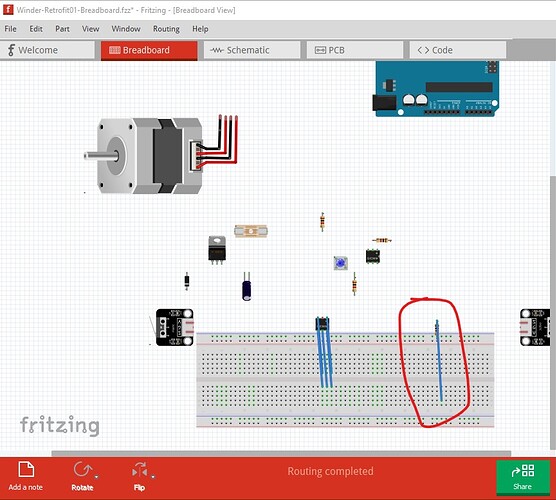
OK, it looks like you don’t have a routing problem, but you do have some wiring errors here. This is a sketch with my corrected motor driver added and wired.
Winder-Retrofit01-Breadboard-fixed.fzz (49.1 KB)
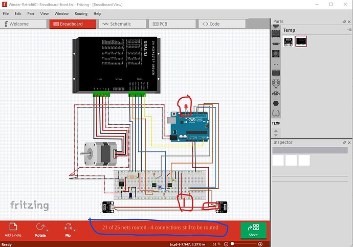
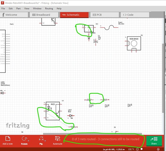
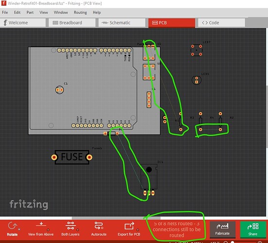
the unrouted nets (circled in blue) indicate there are connections in schematic or pcb that are not reflected in breadboard (or are incorrect!) As well the common of one limit switch doesn’t connect to anything (I suspect but don’t know for sure) it it should be 5V as shown by the red lines. The LED on the arduino needs a series resistor the current connection will draw too much current and potentially damage the Arduino port or damage the LED from over current. Moving to schematic
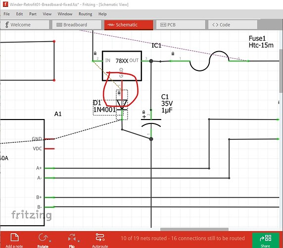
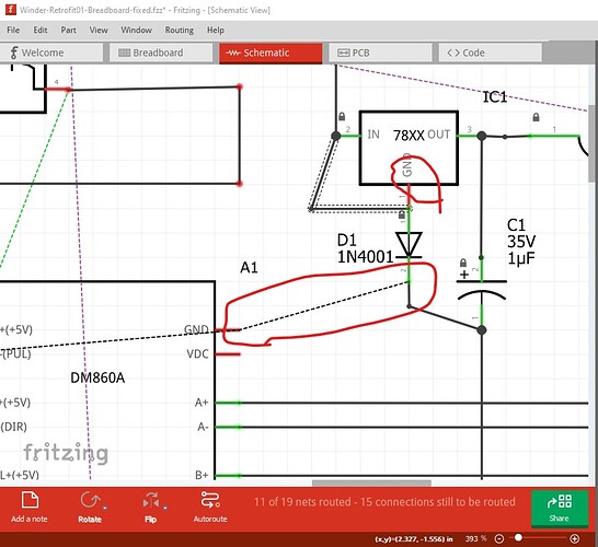
there is no gorund connection on the 7805, and the circled pin shouldn’t be ground (and the diode as wired will short the input voltage to ground which is likely not correct!)
The good the good thing out of all of this is I have found a couple of Fritzing bugs to report (my part should cause an error message, and moving the breadboard in breadboard also moves locked components which both appear to be bugs!)
edit1:
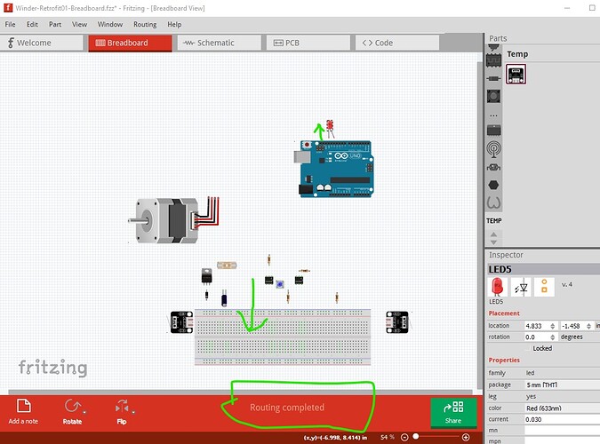
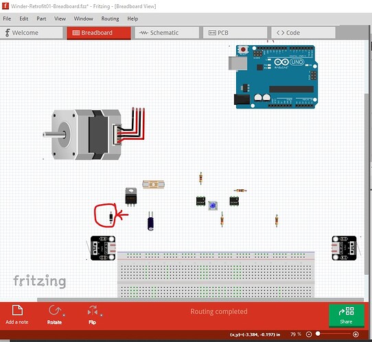
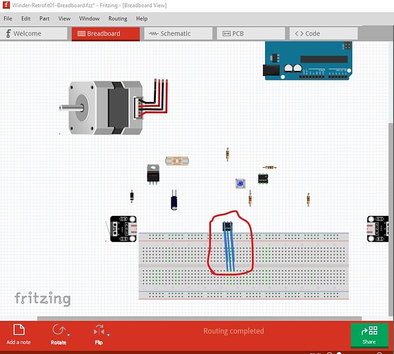
The sketch Winder-Retrofit01-Breadboard-fixed.fzz above in fact appears to be still corrupted. I was poking at this to make a problem report on the issues and as a side effect have perhaps made a better sketch to start from. I started by deleting all traces in all views, then unlocking and moving the breadboard down (so the components on it don’t have connections!) and moved the LED on the arduino up so it is also not connected.
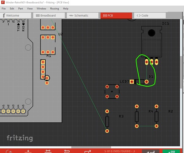
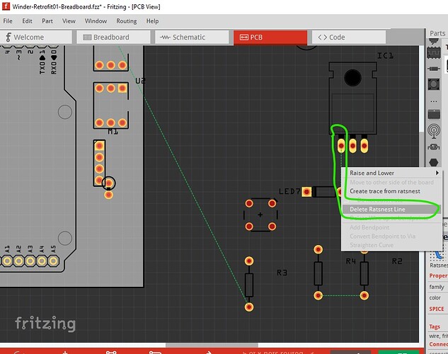
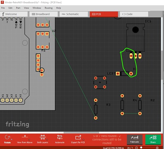
however that still leaves rats nest lines connected in schematic and pcb (circled in green here)
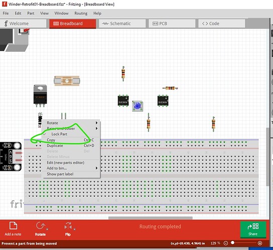
to (hopefully!) fix that select the ratsnest line in pcb and right click and select delete rats nest line. That should clear the routing connection from the database which is what we want. First however switch back to breadboard and verify that the diode is locked (which it is) and thus should not move.
however when I delete the rats nest line in pcb
the rats nest line indeed gets deleted
the diode in breadboard is moved (which appears to be a bug because the part is locked!) Deleting the wire on the IC causes the IC in breadboard (which is also locked) to move and adds wires to all the connections other than the one the rats nest line was removed from.
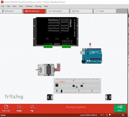
and deleting the rats nest line on the resistor both moves the resistor and makes a connection to the breadboard. To fix this I deleted all the added wires and moved the components and breadboard back to where they started from and loaded my corrected motor driver part to give this sketch which should be ready to be re wired without database conflicts.
Winder-Retrofit01-Breadboard-ready-to-wire.fzz (26.4 KB)
which looks like this
If you do the breadboard wiring completely then do schematic (and pcb if desired) I think you should be fine the database corruption should be cleared. However the safest way to proceed is to start a new sketch and place the components and wire breadboard and then schematic. Hope this helps!
Peter
