Good morning everyone. I wanted to ask if someone has created HORIZONAL momentary buttons of various sizes. I can’t find them in the parts. Possible?
Thanks in advance.
Good morning everyone. I wanted to ask if someone has created HORIZONAL momentary buttons of various sizes. I can’t find them in the parts. Possible?
Thanks in advance.
Welcome aboard. Yes it is possible, although from a Fritzing standpoint there is no difference from a vertical button unless there is a footprint difference. By the same token it is not difficult (assuming you are familiar with making parts which takes a fair bit of time) to make such a change. A data sheet of the switch you want would be a good start. Also both Sparkfun and Adafruit have fritzing part archives on github so if either of them have the push button you want they may also have a fritzing part (although a google search for "fritzing part horizontal push button didn’t turn anything up.)
Peter
Tanks very much  I appreciated your help.
Since I don’t see a data sheet and/or a request for a new part, I assume the horizontal switch has the same footprint as the standard part? It is easy enough (at least for me, probably less so for you  ) to modify the existing push button part to reflect any changes for a horizontal switch, but I need a datasheet to see what needs to change,
Peter
Hi Peter,
i ordered few buttons and i requested the data sheet. Could you please help me in modifying an existing 6mmx6mm tactile vertical button (only che pcb side) to became it horizontal? This is because is comfortable to have the default icon of the component in the breadboard.
The component the component that I would like to modify is called “Pushbutton” family (switch) and package THT (6x6mm).
Thanks in advance.
Sure, do you have a pointer to the .fzpz file of the switch you want to modify? I don’t see anything that is 6mm by 6mm in core parts. If I understand correctly you want breadboard and schematic to remain the same and pcb to reflect the footprint above.
Peter
I use them, sometimes. Main focus is ensuring you get the right length of the Post (the part you push) so, if mounted into a Box/Case, it sticks out enough to access it… Mine are 10mm
Peter,
yes, you understand.
this is the part!
Thanks for the availability.
Pushbutton.fzpz (5.9 KB)
OK this part should do the trick. The moduleId is the same so you will need to delete your current part to load this one.
Pushbutton-horizontal.fzpz (6.9 KB)
Note these pins (circled in red and blue) are connected together. It isn’t clear on the data sheet that is really true … As always print out the pcb footprint at 1:1 scale and try it against a real part before ordering boards. The silkscreen should have the button in the correct place.
Peter
Great!
I understand Peter, i must connect in the real PCB all of the pins!
Thanks!!!
While the data sheet is unclear, I think that only J3 and J1 would work. If it is like the other tactile push buttons there is an internal connection between J1 and J2 and J3 and J4 inside the switch, but it would be best to check that with an ohm meter before depending on it. It may be that J3 and J4 pins are only for mechanical strength with no electrical connection, or that they connect to the other pin (in which case the part needs to change!) without a part in hand I can’t tell.
Peter
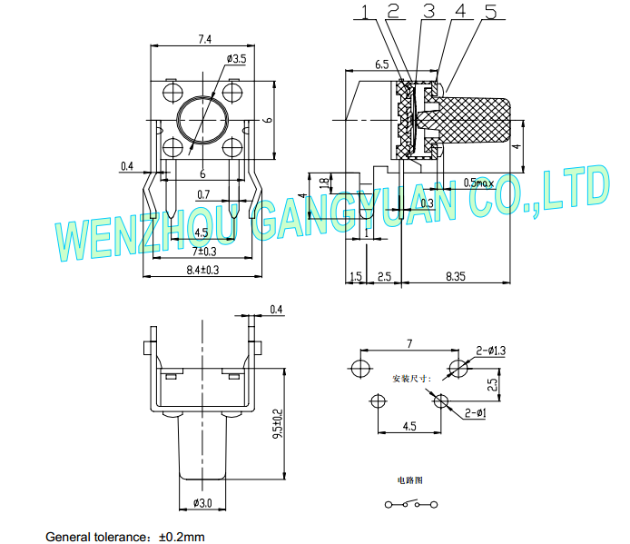
I am using the same button. Look just like the one on @opera_night’s image. Different manufacturer, but the data sheet is nearly identical.
This is only a SPST button with 2 pins. There is no connection between J3 and J4. The other two pins are just clips on the housing for fastening to the PCB. The part posted above was based on the 4-pin pushbutton from core, that’s why there are four connectors in two busses.
Since I need this with a top view, I have redone the part, this time based on the 2-pin pushbutton from core. The breadboard view is top view, the schematic is used from core (since nothing changes), and the PCB is not entirely identical to the ones above, as the pads for the clips have narrower copper.
The icon is new and can be used for any 2-pin horizontal pushbutton variant.
This one is not done with the part editor, but manually. (Except for the icon, that was done in Inkscape.) I did try to import it into Fritzing, which worked. But let me know if it doesn’t work for you. Just in case it only worked for me by chance because Fritzing already new the part from construction or something. I have no idea.


Pushbutton_2_horizontal_835_topview_1.fzpz (6.1 KB)
Btw, size-wise the top view and PCB view are for a 8.35mm variant.
I ran this part through FritzingCheckPart, and was “going” to report that it was missing the schematic svg. However, it works just fine. It successfully picks up the schematic image from the core part library. Nice.
Good part.
It turns out that core schematic image file is not following the rules. It has px for drawing units, and zero width terminal graphic.
@vanepp Looks like another adjustment needed for FritzingCheckPart. If an image file specified in the fzp file is not found with the initial (local folder) lookup, try looking in the svg/core/viewname part library folder. May need to locate and read the Fritzing configuration file to accurately determine that, or even use an extra command line option to point to it. Equivalent to “–parts” for the fritzing app.
Interesting! I didn’t know Fritzing would do that. I’ll put that on the feature list!
Peter
Ah, yes, this does add complexity to the FritzingCheckPart. I didn’t think of that.
I actually found that to be a neat feature, since schematics are certainly something that can be reused from time to time. I also named the icon SVG with a more generic name, for that reason.
I’m not sure the use of px is a real problem in schematic view, is it? Maybe to get the 0.1 inch spacing right, to match with the grid in Fritzing? That’s the one reason I could think of.
Also is there a real problem with zero width terminal graphic other than not being able to select it in Inkscape? (Which still works via the XML editor.) I did put terminals into the breadboard view to make it snap properly to the breadboard, and did use a small width, but working only with the XML file actually makes it not really necessary.
But as you note, it also adds capabilities (and simplifications) to creating custom parts. svg files are only needed for views that do not existing in the core parts. icon, schematic, and pcb footprint are all reusable in many cases.
Using this IS going to add a complication for fixing and updating existing parts in the core library. Changing svg files can affect parts that can not be seen. From my current understanding of the way the code works, obsoleting a part (with the svg images) should not break an external part. The ‘lookup’ should find the obsolete image and use that. Modifying an image in place is more risky.
That is the usual concern. With ‘px’, Fritzing uses code to determine what the physical units should be, and there are cases it gets it wrong, because the svg drawing editors have changed the interpretation over time. As long as the svg includes the normal source ‘tags’ added by the editor, it has a good chance to get it right.
Not that I know of. A lot of people use Inkscape though, and many are not comfortable with the xml editor. It is preferred that not only do parts “work”, but that they are also generally usable as a base to create more parts.
I use (an external) xml editor as well, but I make the terminals small squares, offset by half their size, to get them to center where I want. The center point is what Fritzing uses to ‘snap’ the wires to.
Me either. I have some parts on my list that can benefit from this. It also added to the list, to add some more generic images to the parts library, even if they are not currently being used in a (core) part. Some standard directly reusable footprints, icons for packages, schematics would reduce the work needed to create parts. And possibly improve consistency. If we can get “good” images in the library, and use them.
For cases where the only difference (to a core part) is the pin ordering, only an fzp file should need to be created. FCP would complain (even if it found the core svg files), but mapping the appropriate pin and terminal id to the connector number for each svg file should be all that would be needed.
But it also brings the benefit that improvements and corrections on core SVGs are immediately reflected on user parts.
Ideally this would help creators to make parts, as they don’t have to bother with getting certain views right. But on the other hand this only works when creating the part manually, which probably already means having some deeper knowledge about making Fritzing parts.
By the way, when exporting a part from Fritzing, it does include the SVG from core in the .fzpz file. I explicitly removed the schematic SVG from the .fzpz zip file after export. I did not want this to clutter up the svg/user directory, maybe causing problems later when the core SVG is updated.
When importing the part, did Fritzing copy the core schematic SVG into your user/svg directory or is it simply left missing from the svg/user/schematic directory?
Coming to think of it, most of the top view parts made for core parts could be done this way.
Then again, my dream would be that Fritzing includes another view, like “perfboard view”, in parallel to the three existing ones, and every part also has a top view SVG included as a fifth SVG.
Only if the changes are purely graphical. Anything that (also) needs changes to the part definition (fzp) for that view would cause the custom parts to break.
A quick check shows that there is no related svg in the svg/user/schematic folder. Which is I expect why this works. Fritzing likely has a “path” that it searches for the svg images of a part. Once the fzp file is found, it probably does not care any longer that it was stored in the user folder. It just starts the search for each referenced svg image using the full path, which will include core, contrib, user, and obsolete.
Yes, and parts with alternate footprints, like narrow pads instead of circular.
Absolutely. But things like “we all now use 200 thou instead of 100 thou for pins” or grid alignment or fonts stuff, etc. is something I could see. Isn’t that what most problems with old parts in the core library are and also what people like to get wrong?
Ooooh, or a RGB LED with different pinout. That just gave me an idea, I think I have one like that.
Changing the spacing and/or locations of connection pins in an image would not break “PARTS” that use the image, but it WOULD break any sketches that have the part, where wires are connected to the pins. The wire end points are stored in the sketch, and would not automatically move. Which is one of the reasons for the warning to check the part in all views when updating to the new version of a part that has been rolled out with the library. Changing the size or location of text (in at least schematic view) can also (I think) mess up existing sketches that have the part flipped or rotated. There is a lot of potential for unexpected ripple effects with simple changes. About the only thing that is “safe”, is minor changes to stroke width or colors. Or graphical changes not related to connectors, that do not change the bounding box of the part graphic.