Hello,
Please, I need help to build a PCB, clone pro micro atmega 32 u4 16mhz 5v, the making of the PCB, on the board would fit and unseat the PCB board.
Sorry to be asking, I’m new here on the forum, my knowledge of electronics is little, I only know how to do welding!
I am already grateful for any help !!!
Take care, people !!
malpaso
Welcome aboard! Why would you build such a board? You can buy an already built board for less than the cost of the pcb alone, for example (one of many) this one:
5 boards from a cheap board house in China are around $20 before you consider the cost of the components (and the expertise needed to connect them.)
Peter
Hello Peter,
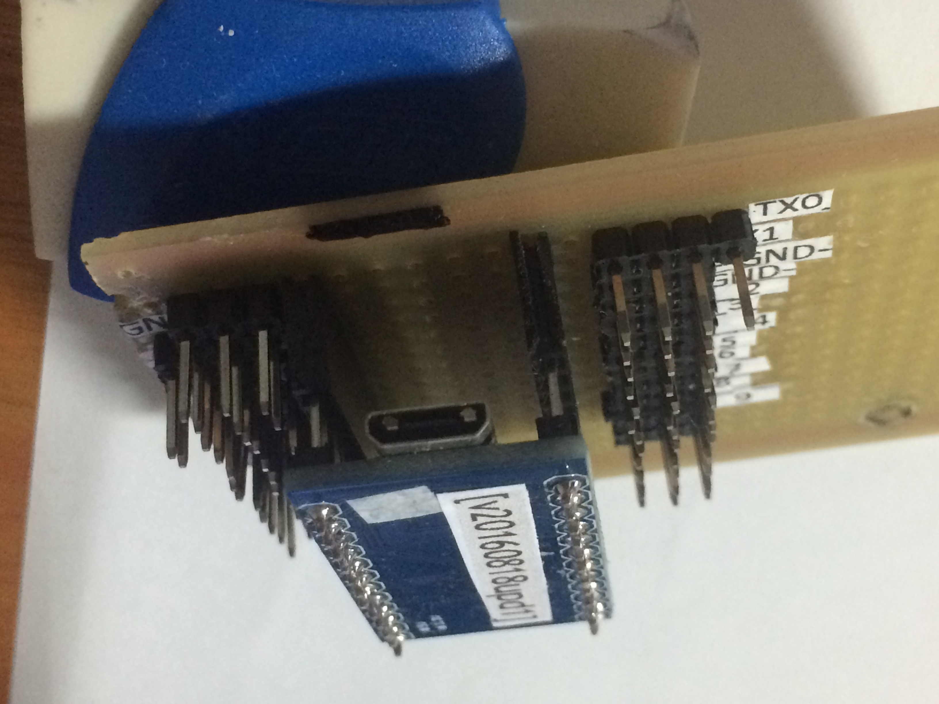
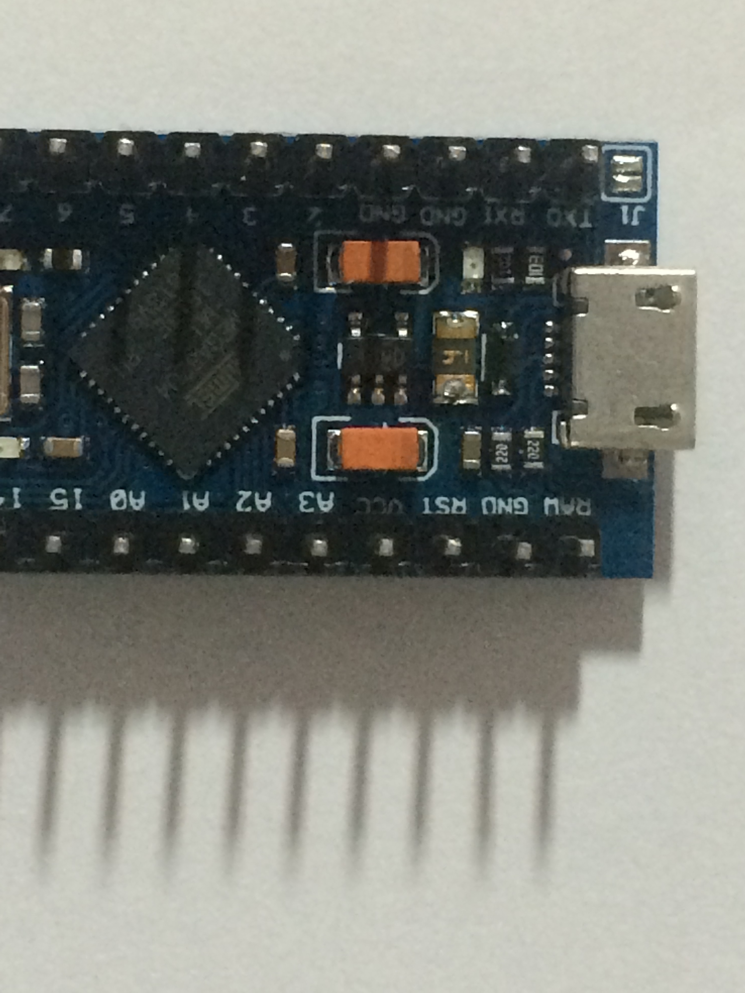
thanks for answering, i have the pro micro card, i need to build PCB, to connect Pro Micro, there are several dupont to connect!
IMG_0669|666x500
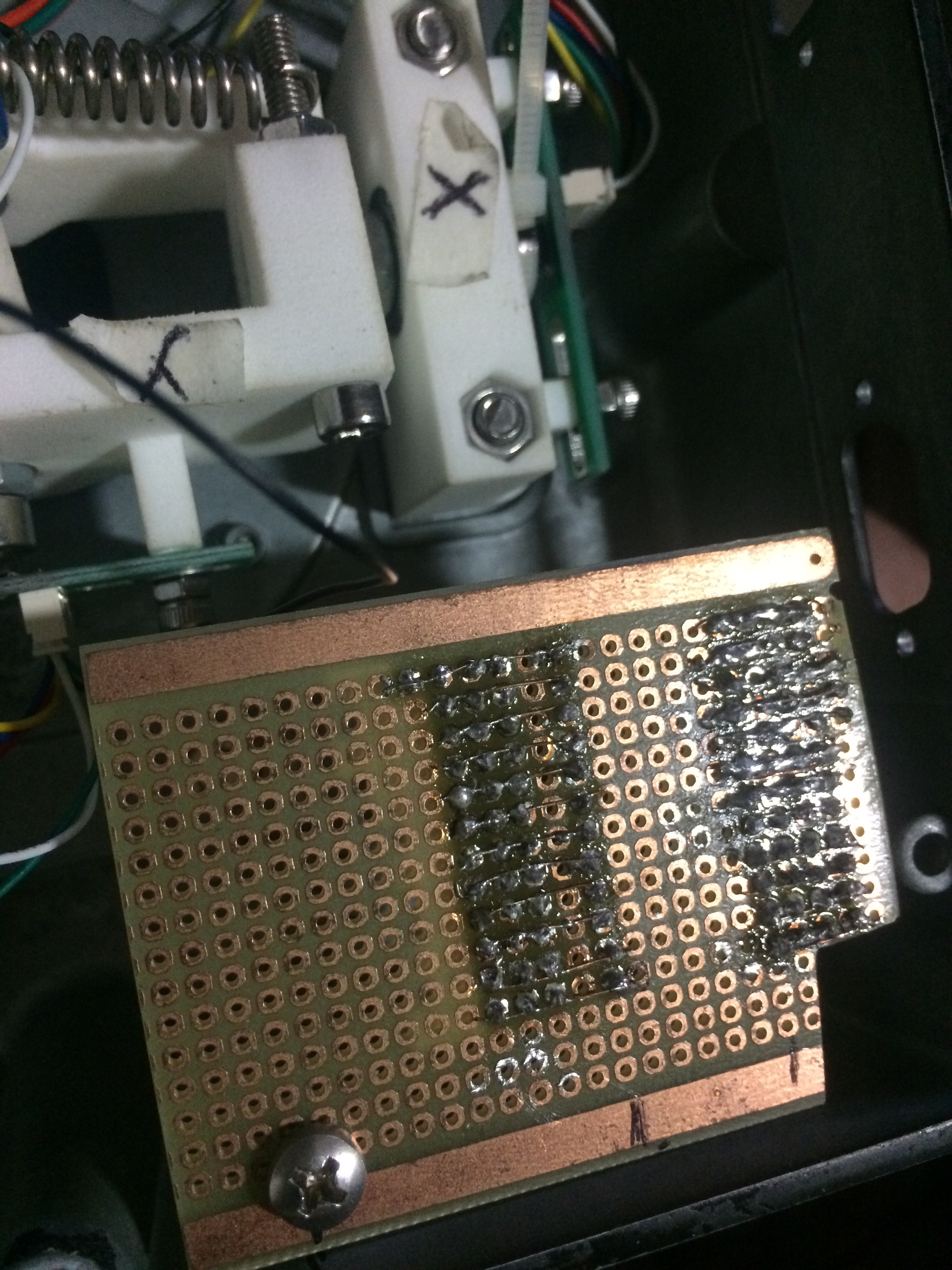
you saw the photos, the PCB is very simple, because I have to connect several dupont wires !!
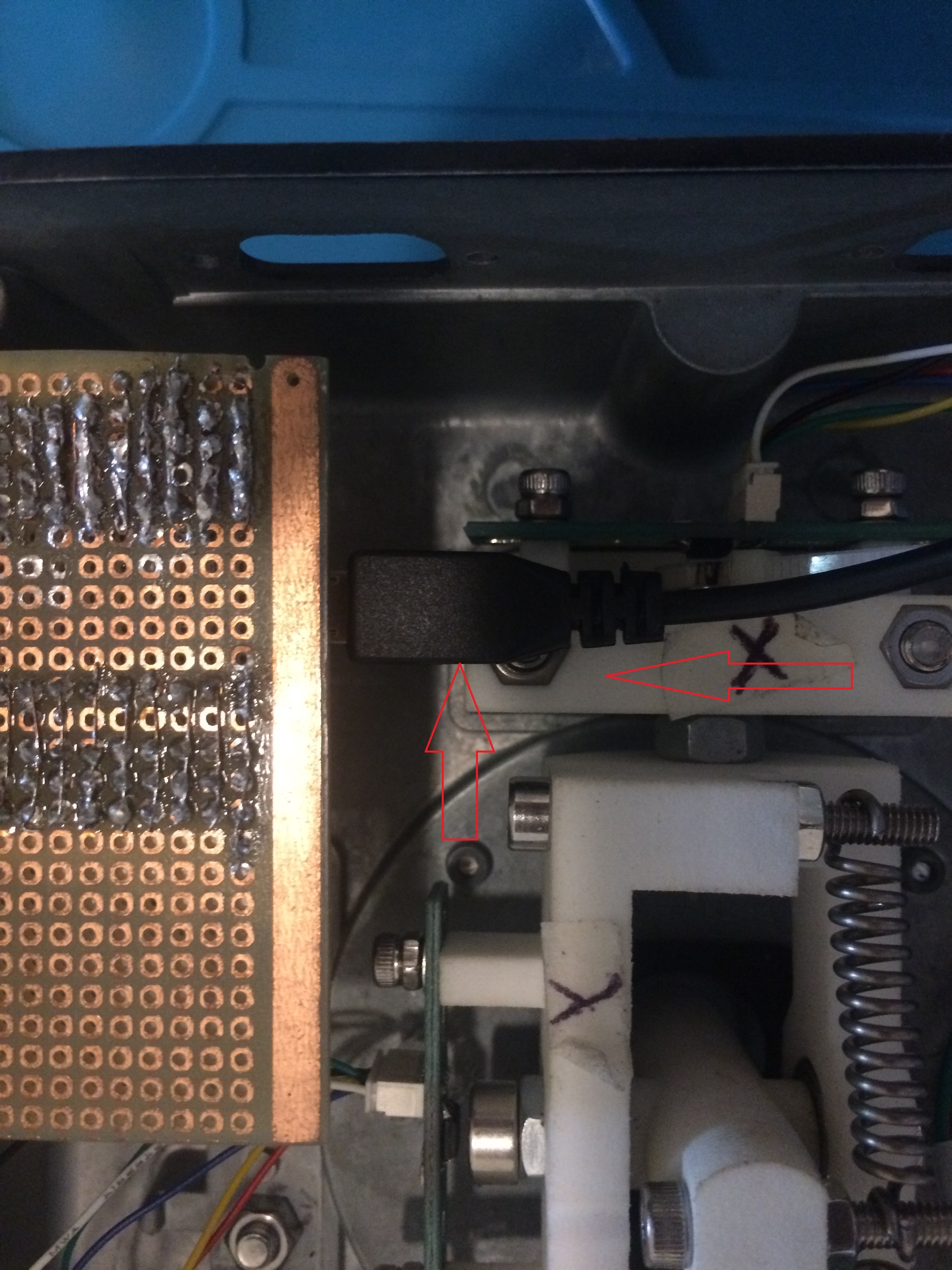
this is from my Hotas Cougar joystick, it’s a mod that I’m applying to it, with the PCB, I do a very clean project assembly!
Take Care !
Thanks !
malpaso
Ah! This is fairly easy. There is a Fritzing part for both the pro mini and the headers. You need to drag a default 2 pin header and the pro mini (both in core parts) in to the sketch and use Inspector (the lower right window) to change the number of pins to get the headers of the length you need. Then connect the pins of the mini to the appropriate headers. If you run in to problems upload the sketch (the .fzz file) to the forum (as you did the photos) and one of us will look it over and help you out. This is much easier than trying to make a cpu board  .
.
Peter
I got lost, I’m not getting it, is there a video tutorial ??
Thank you, Peter !!
sorry for my stupidity!
Not stupidity, but rather ignorance which is correctable. This stuff is complex, I’ve been doing it for 50 years now, so it is much easier for me. Unfortunately that means I don’t know much about the introductory documentation, because I was already familiar with similar programs when I started Fritzing (but it took me a couple of years to lean to make Fritzing parts correctly.) The good news is that Fritzing is easier than any of the others that I know of. A google search for “using Fritzing” turns up a couple of videos (I don’t know how good they are though.) Hopefully some of the other folks here will share what helped them get started with Fritzing as well.
https://fritzing.org/learning/
is the official documentation site. As I recall (it has been a few years since I looked at it) it is pretty good, but again I was already familiar with such programs which makes it easier for me. Fritzing was originally designed for kids which is why it is simpler than the other options, it tries to be as easy to use as possible as a result and it is well designed. Good luck and feel free to ask for help here!
Peter
Thank you for your patience, with me, I will look at learning !!
I really liked Fritzing, I already watched some videos, very interactive!
Although I don’t know, where to find some of the menus!
Thank you, Peter, we will talk again soon!
Take care there !!!
malpaso
This may help some. I started a sketch and copied in a pro mini (since it is a little difficult to find) then created some headers as an example. I’ve included the .fzz file at the end with all the wires removed (right click on the wire and select delete to remove one).
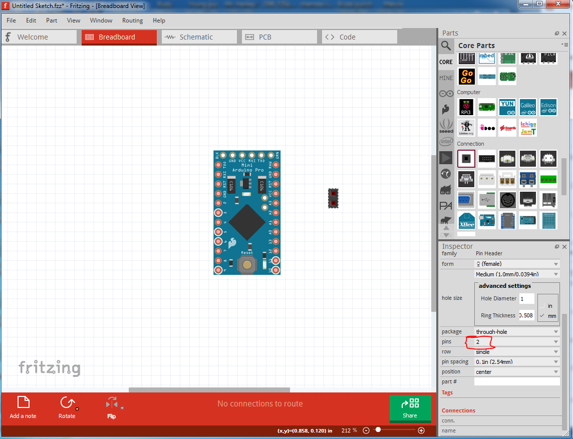
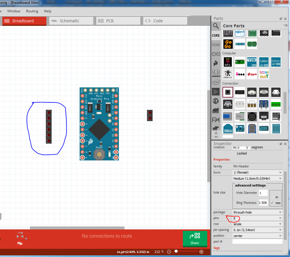
This is the pro mini and a single 2 pin header from core parts. Then I right clicked on the header (circled in red) and clicked duplicate to make a new one. Fritzing creates it at some random point in the sketch (ovelapping the pro mini in this case) so just click on it and drag it to a better position (it is sometimes hard to find them if there are a lot of parts in the sketch!)
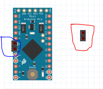
Now I used inspector (the lower right window) to change the 2 pin connector to 6 (circled in red) which creates a 6pin connector (circled in blue)
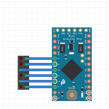
Now I dragged the 2 pin connector over to make a dual row connector (as in your photos) and made them both 6 pin with inspector and clicked on a header pin and moved to a mini pin to create a wire between the pins.
Now I will switch to PCB view. Initially the parts are positioned at random and the headers are positioned on top of each other so there appears to be only one.
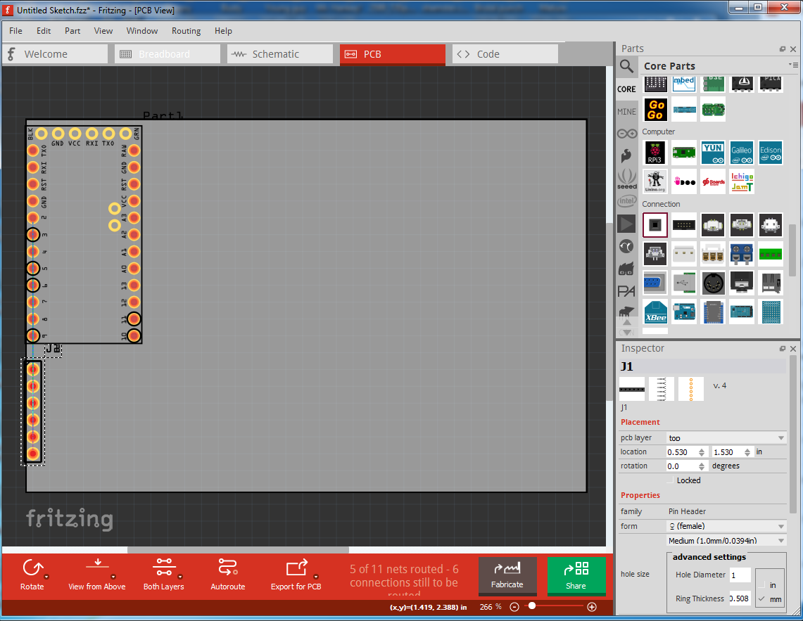
So the first thing to do is reposition the parts to a sensible order :
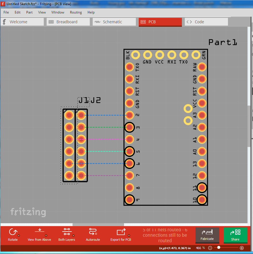
The colored lines here (called rats nest lines) reflect the wires that are connected in breadboard view. If you double click on one it will create a trace on the pcb. What you need to do is duplicate your perf board layout with headers in breadboard and run wires so that the header pins are connected the same as your perf board. Then drag the parts in pcb until the layout matches the perf board layout and click on the rats nest lines to make traces (you will likely need help doing that, so post the sketch when you have breadboard complete.) Because changes in pcb will reflect back in to both breadboard and schematic it is best practice to complete one view (breadboard in this case) completely before moving on to the other views. Here is the sketch file with just the parts (no wires) to start from:
pro-mini.fzz (1.3 KB)
Peter
1 Like
Hi Peter,
I’ve been working on Fritzing, please see this file !!
Thanks!
malpasopro-mini MP.fzz (2.6 KB)
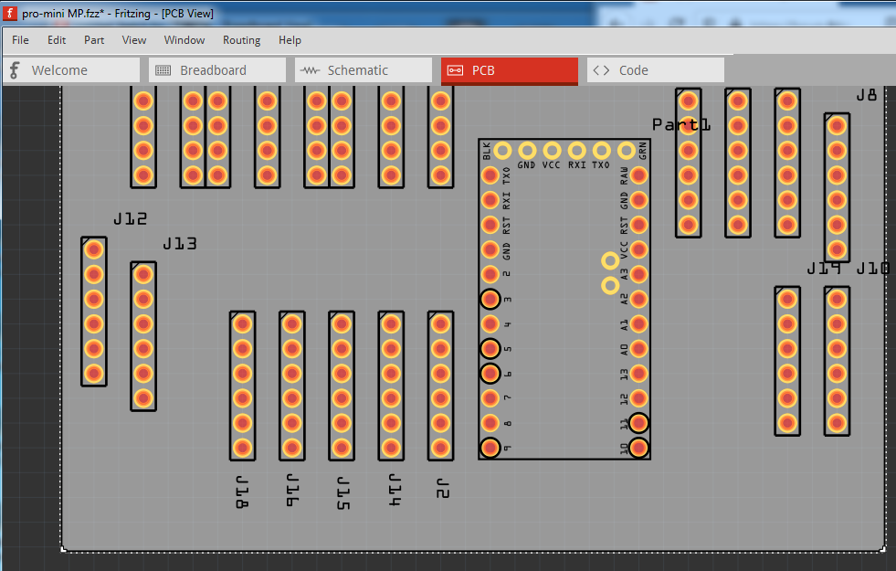
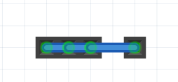
Looks good, is the intent to make all the connectors connect in a row like this (this is in pcb with the connectors spaced apart to make the connections obvious?):
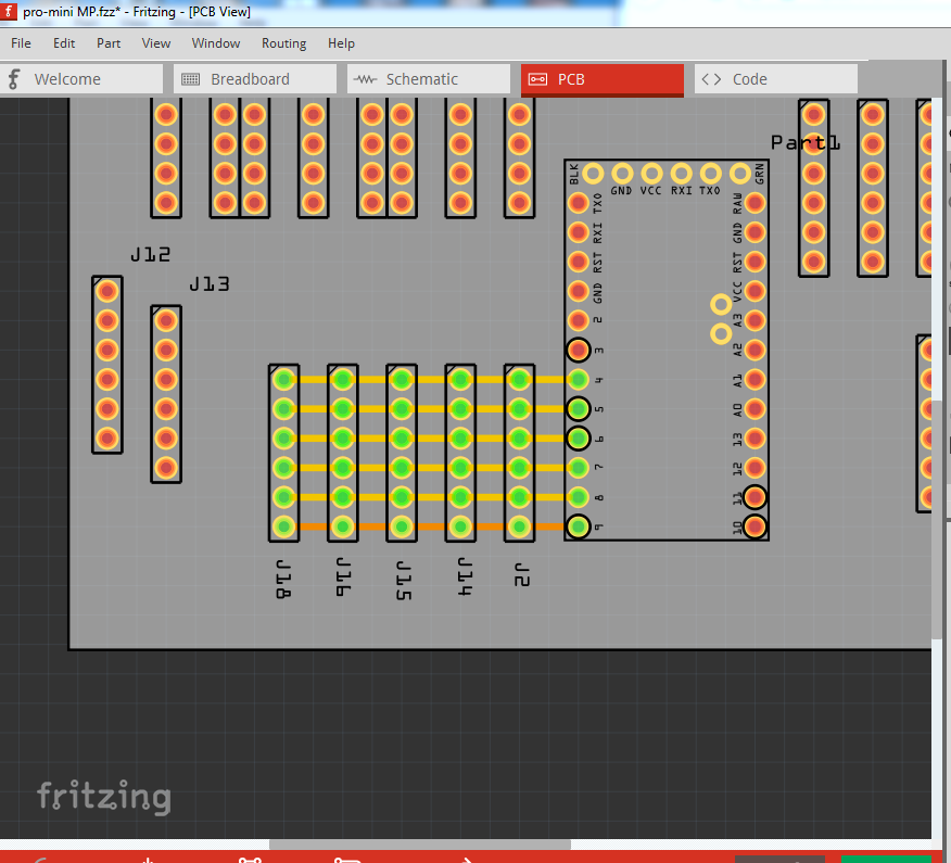
Here connecting to any of the headers on the bottom row will connect to pin 9 on the Pro mini. Here is the same view in breadboard where the rats nest lines are indicating the connection (moving the headers closer together will make pcb identical):
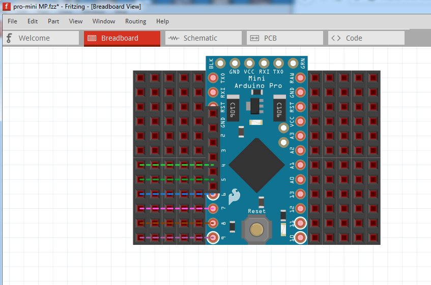
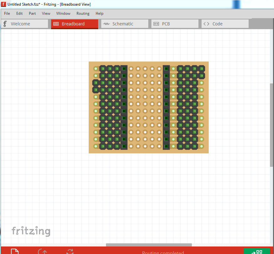
If this is correct, I think changing to perfboard in breadboard will probably be easier (if a little tricky.) Here in breadboard view I have clicked on the perfboard in core parts (circled in red on the right of the window) and dragged it in to the sketch:
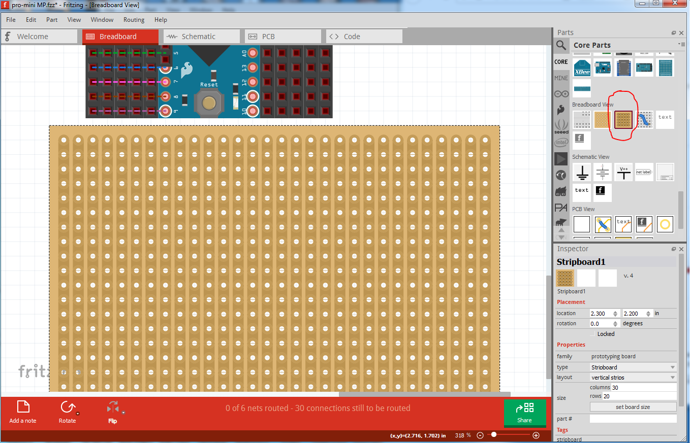
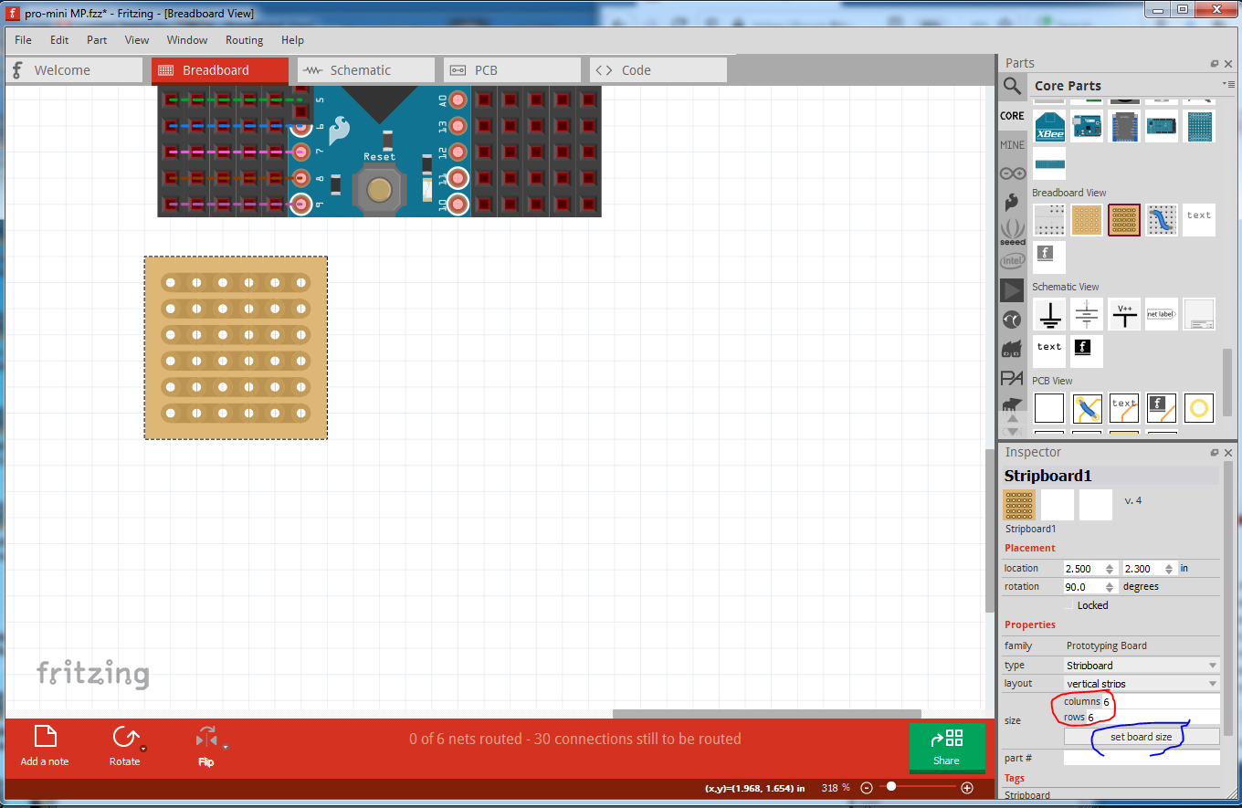
currently it is oriented wrong and too big, but I can fix both of those. First right click on the perfboard and select Rotate->Rotate 90 clockwise to change the orientation. Then we need to change the default 30 columns by 20 rows to 6 columns by 6 rows then click set board size (circled in blue) in inspector so the perfboard will fit under the headers and connect to the pro mini pins, like this:
In PCB view I deleted all the wires so there are no connections (we will make them in breadboard with the perfboard.):
Unfortunately to get the perfboard to connect to the pro mini, I need to use a wire between the two like this (putting the perfboard on the pro mini pins does not connect) but it works as I think we want in pcb which is the important part:
and in PCB view the rats nest lines (which we can turn in to traces) indicate the 5 headers across connect as we desire:
Does this look like what you are trying to make? I may have not understood what you need.
Peter
You are having a lot of patience with me!
The inspector has disappeared from the property bar, strange!
See Copacabana Beach in real time, temperature of 28 degrees Celcius, the beach is empty, summer is over, there is no one on Avenida Atlantica, at the peak of summer the temperature hits about 42 degrees Celcius !!
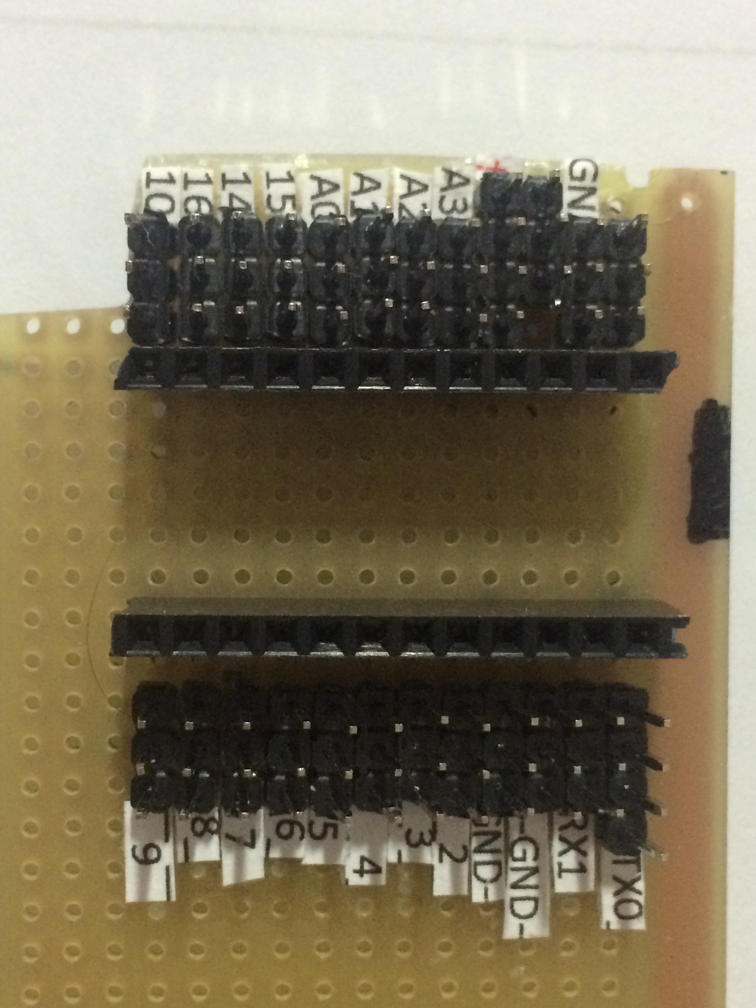
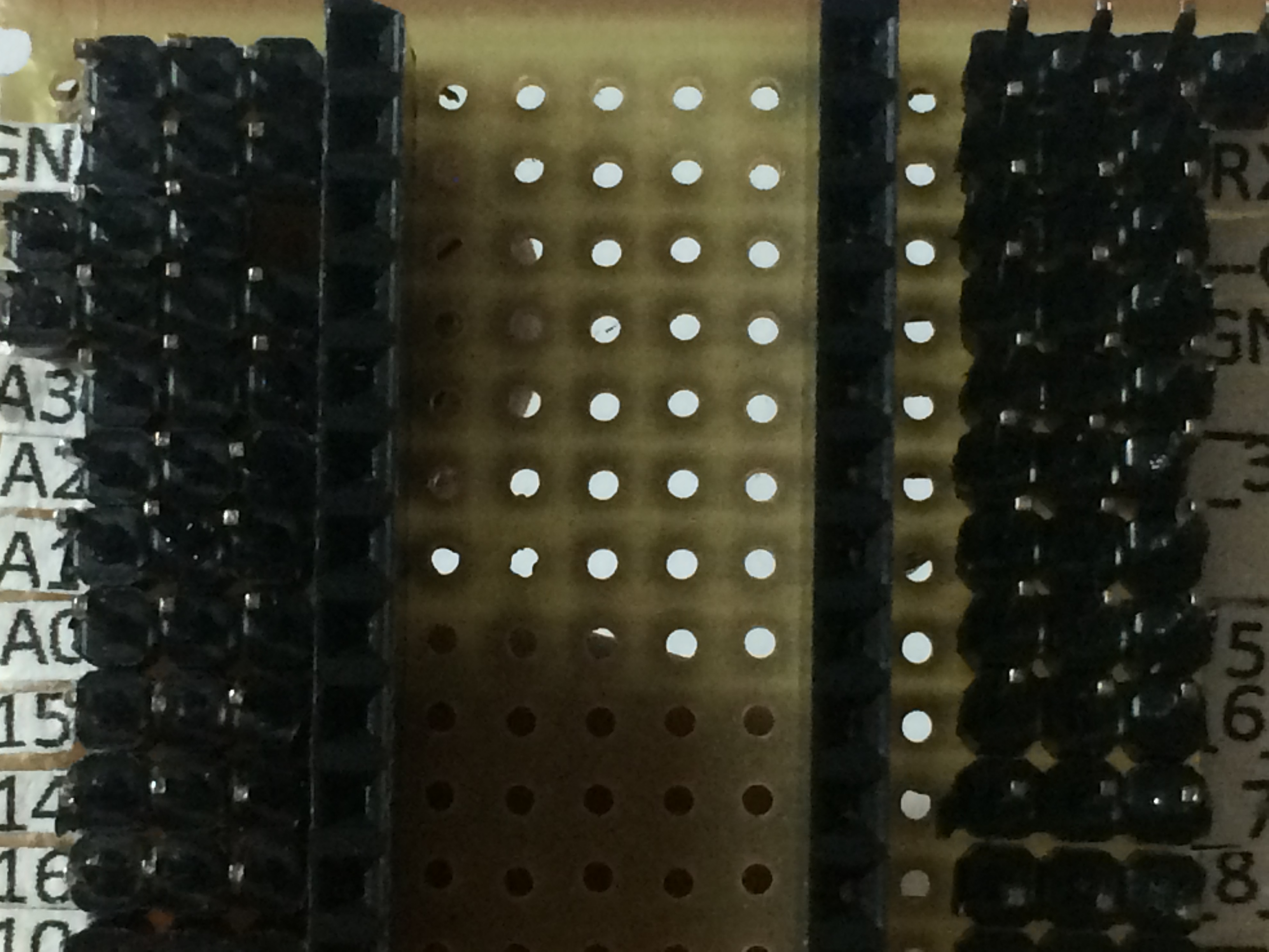
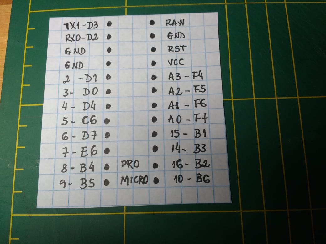
What I need is a picture of the bottom of the perf board to see how the bottom of the header are wired. I assume (perhaps incorrectly) that that the 4 pins in the row marked 16 in the last photo all connect together like this:
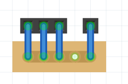
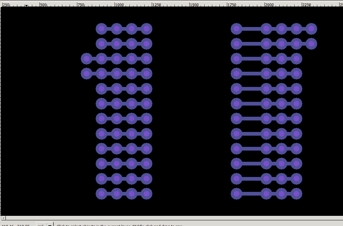
Here the headers at the top match line marked 16 in the photo. I am assuming that as shown in the diagram above all 4 headers connect to each other so that plugging in to any of the 3 headers will also connect to the pro mini pin. That connection is what we need to produce on the pcb so that it will work the same as your perf board part. Fritzing needs to know what pins are supposed to connect together in order to make the pcb do that for you. Here is another view with only the headers, connected as I think you want them with wires:
The blue in the picture indicates wires connecting the pins together. On the pcb that will be replaced by a strip of copper to make the connection.
Peter
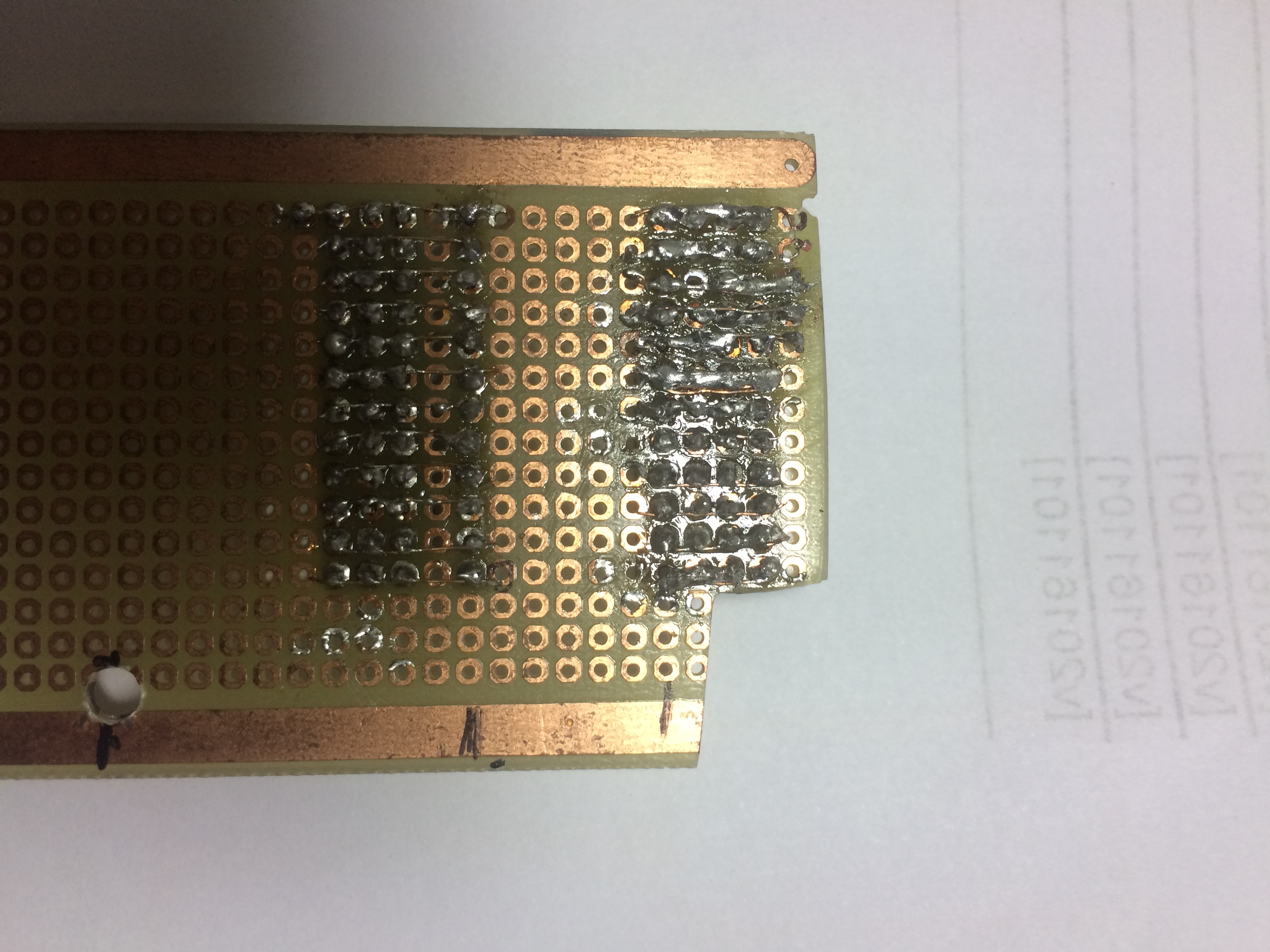
Looking at you from the front, the welding on the right, was not very good, my soldering iron has a broken tip, the trade is closed, I can’t buy another tip !!
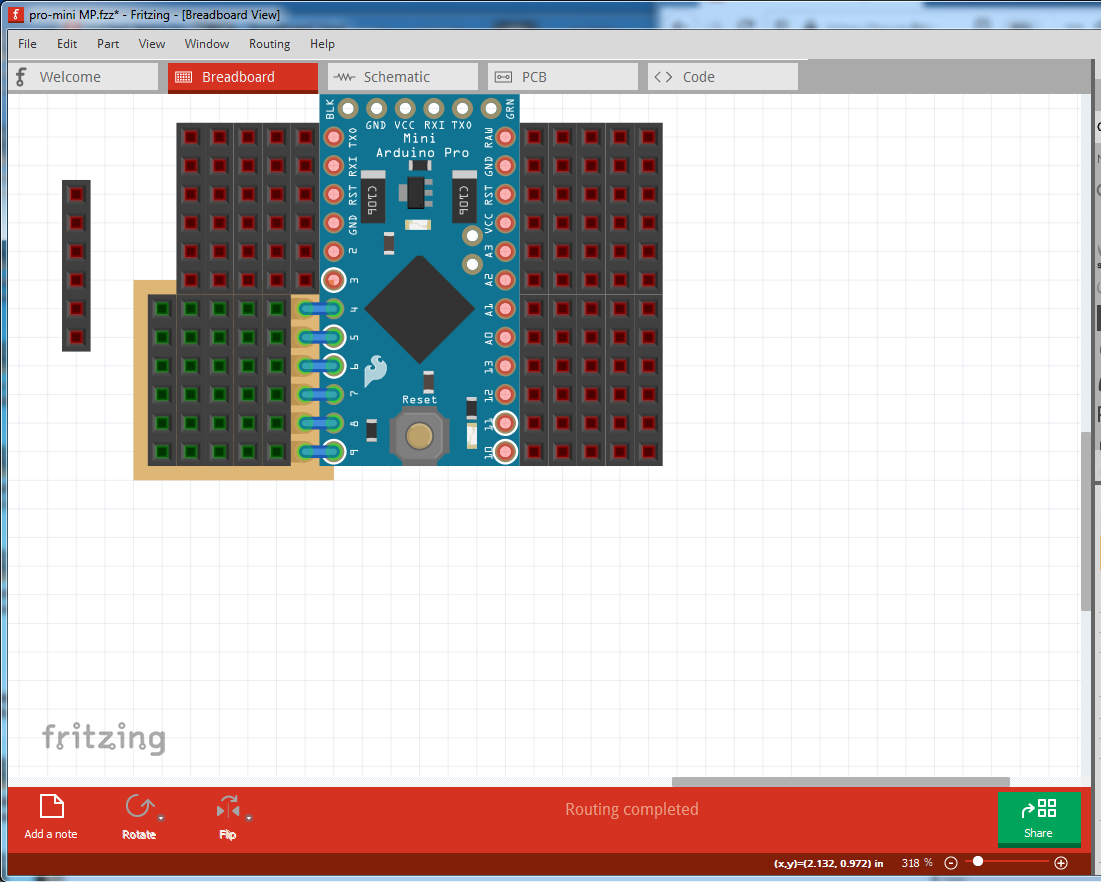
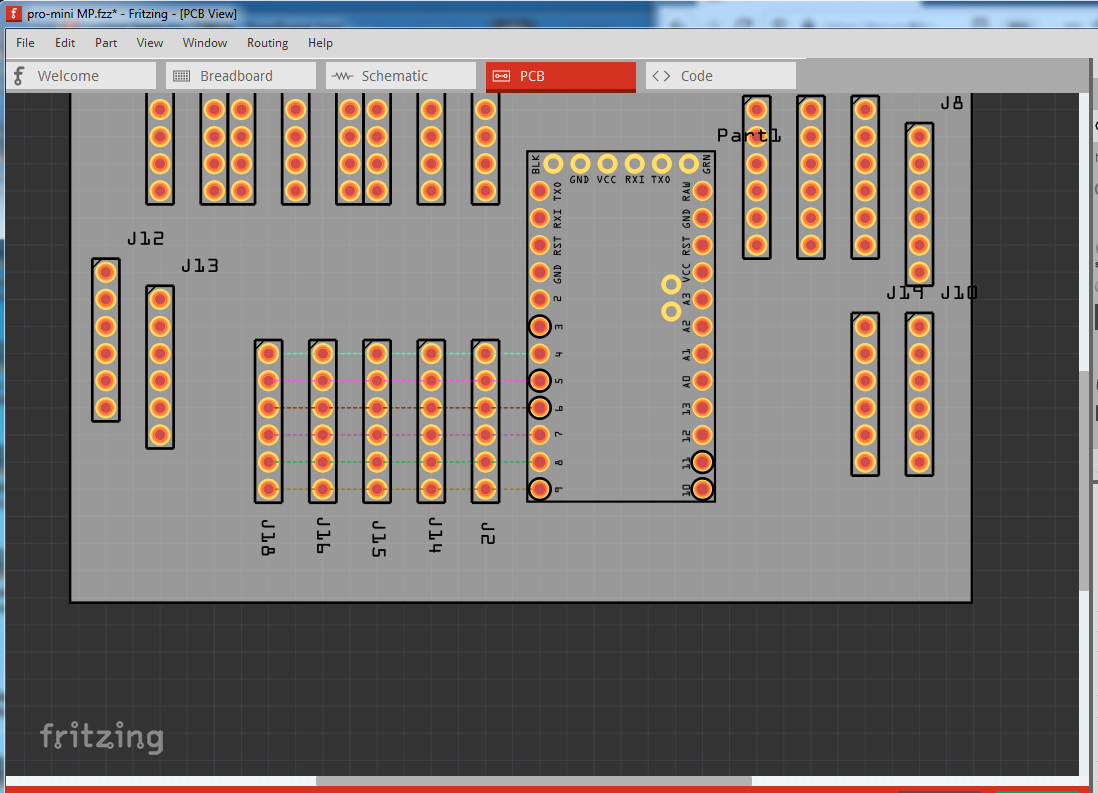
Yes, it looks like what I expected, that the connectors all connect in a row as in the diagram in the last post. I think this sketch implements what you want. I deleted the pro mini in this as it is only causing confusion. In breadboard I changed the headers from female (which only the pro mini is) to male and put them on perf board to make the connections. Then in pcb I moved the headers to be in the correct place and clicked on all the traces to complete routing in pcb giving this:
breadboard:
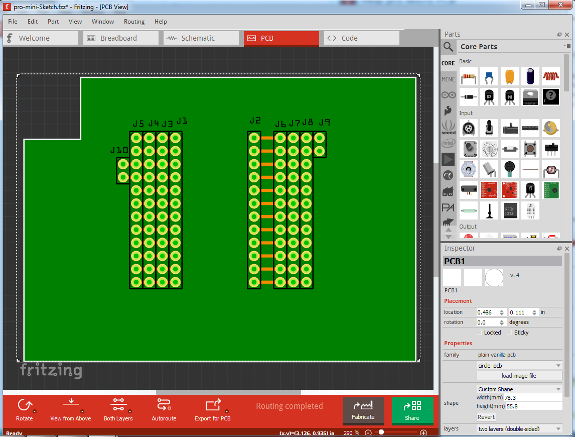
pcb

Which will look like this as a pc board:
The paler circle in the pads indicates where a hole will be drilled. All that should be left now is to set the dimensions of the board and the position of the hole for the mounting screw in pcb as in the picture in post 3 of this thread and you should be good to go. Here is the sketch that the above images are from:
pro-mini-Sketch.fzz (14.4 KB)
Peter
1 Like
Hello Peter, how are you?
I’m sorry I didn’t show up on the forum, my brother tested positive for Coronavirus, we had here at home, to find a room for him to be isolated, from the others !!
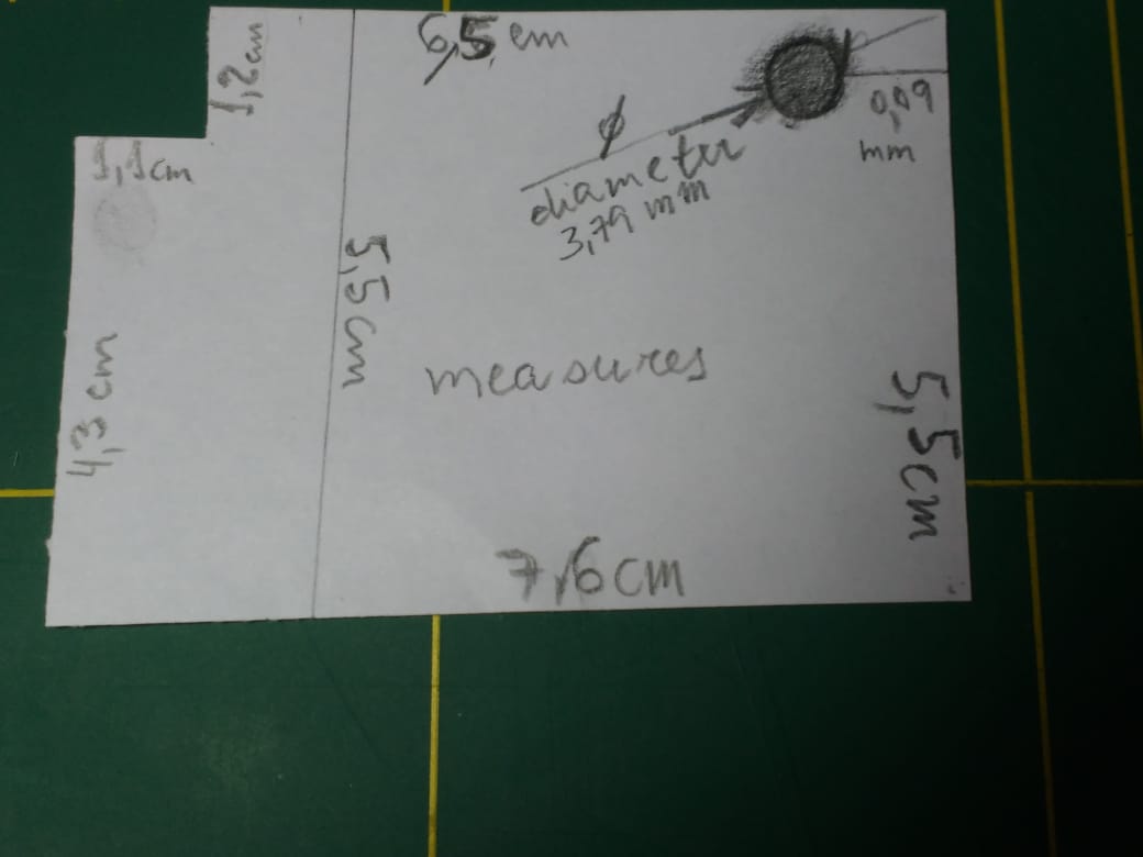
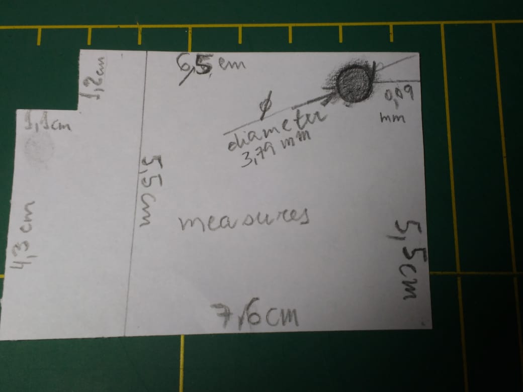
Peter follows photos, the measurements of the PCB, a question is possible to write on the PCB, I am attaching another photo for you to see!
All holes have a measurement of 2.54mm, except for the screw that the measurement is in the photo!
Dimensions (LxWxH)
33x18x3mm; (without pins), from Pro Micro
I would like to thank you immensely for helping me, my friend !!
Take care, there !!!
Please if you have any questions, ask !!
Best Regards !!
malpaso
Not a problem. family comes first! Hope your brother recovers from this horrible thing, so far (although I expect it to get much worse) things are under control here.
Yes in the sketch you can add text (such as labels for the pins) to the silkscreen layer and they will appear on the board. I’ll add some text and how to do it for you. The only further measurement that I need is where the pins should be in relation to the edge of the board, although one of the photos above should give me that information. I’ll try and figure out how to do the outline (I’m usually not all that good at outlines) and post in a bit.
Peter
@microMerlin @opera_night can one of you show me what I am doing wrong in this board outline please?
outline svg file:
![]()
sketch:
pro-mini-Sketch.fzz (14.8 KB)
It looks fine in Fritzing:
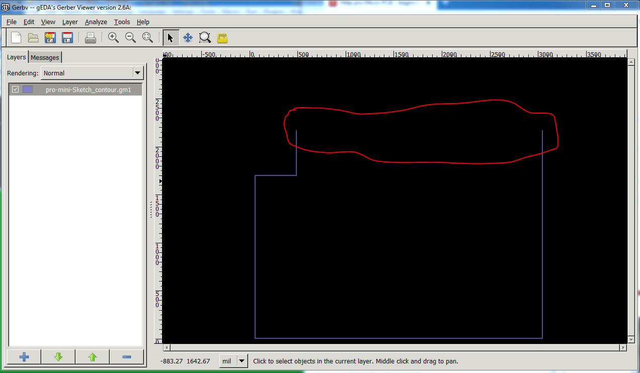
but the gerber output contour file is missing the top line and I can’t get it to appear. Help please!
Peter