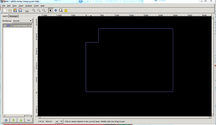
It also looks fine with SVG exports, including etchable too. I do not have experience with gerber files. An idea though. That missing edge matches the closing line segment for the silk screen path element in the exported SVG. Perhaps the gerber export is not seeing the close. In the SVG export, that is a trailing “Z” (upper case), where I would normally use a lower case “z”. Maybe change that manually in the source pcb image. Next, since that is the closing edge, try starting from a different corner (the inner notch corner), and see if the missing edge moves. If it does, a fudge would be to explicitly add that last closing point, instead of letting the “z” close it for you. Which could be done by manually replacing that trailing “Z” with “L” followed by the coordinates of the initial move point. Nothing I see looks wrong. This is just fudging to maybe get it to handle that segment differently.
Thanks I’ll try that. I think this may be a bug that kjell fixed in the development version (he found 5 different bugs in this area), but that doesn’t help the OP who only has 0.9.4. I think the uppercase Z is the absolute coordinate version of close (z being the relative version) but I’ll try all three suggestions.
Edit: Excellent call! It is the Z that is doing it. Likely it has to calculate the endpoint due to stroke-width and other factors and the fp round off breaks a comparison in Fritzing. Changing the d field in Inkscape to add the L gets changed on save for some reason, so I had to do it in a text editor but with d
M 438,4.88 V 476.88 H 5 V 2169.88 H 438 2997 V 4.88 L 438,4.88
(I rounded off while I was there) the gerber contour file is now correct, so thanks!
Now on to finishing this board!
Peter
Assuming I have interpreted the photos correctly, this should do what you want.
pro-mini-Sketch.fzz (15.6 KB)
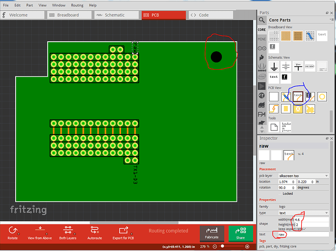
I have added a couple of the text elements to show you how. To add more click the text icon (circled in blue in this image and drag it in to the sketch. You need to then right click it and select rotate 90 degrees clockwise to rotate it (or change the rotation field at the top of the Inspector window from 0 to 90) to get the text rotated correctly, then drag it in to position. The shape field in inspector lets you set the size, I changed it from the default 3.something height to 2mm to fit more easily. The mounting hole is set to 3.79mm diameter, but is probably in the wrong place (I couldn’t read the value in the hole) you can drag it in to the correct position by clicking on it and dragging it, or by adjusting the location bars in the Inspector window. I would advise printing the pcb view out at 1:1 scale probably on to a transparent plastic slide and compare the holes to the perf board to make sure the position of everything is OK. Once that is all OK you should be ready to produce a board.
Peter
Hello Peter, how are you, I hope you are well!
Please watch this video, link below !!
If you have any questions post here!
I think you have to change the position !!
May you have a good day, my friend !!!
Thanks!
malpaso
I see I have the cutout backwards. I’ll correct it and repost the sketch.
Edit: OK here is a new (hopefully more correct  ) sketch.
pro-mini-Sketch.fzz (8.1 KB)
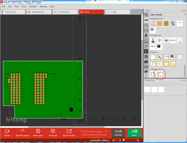
This should be correct (I hope!) As well I have included rulers (the source of the rulers is circled in red.) You can use the rulers to position the hole (it should be close to the correct place) and/or the connectors if needed. You may need to click View->Align to grid to be able to move the connectors off the grid (the hole appears to be off the grid)
Peter
Hi Peter !
Let the situation calm down at home, I’ll take it easy!
Take care there you and your family!
Thanks !!!
malpaso
Not a problem, and good luck! When you are ready to proceed, feel free to post again.
Peter
Hello Peter, how are you, my friend?
I wish you and your family a Happy Easter !!
Times are very difficult !!
A Happy Easter to everyone on the forum !!!
We have to make a difference in the battle to defeat COVID-19 !!!
Thank you for your help and support and stay safe !!!
Best Regards,
malpaso
So far all is well here. The local government thinks they have a handle on the outbreak, but the next few weeks should tell. Hope all is going well for you!
Happy Easter indeed!
Peter


