I don’t mind trying fixing it myself, but I’ve tried to look in the parts editor and I tried unzipping the .fzpz file and look in the fzp (xml) file, but I cannot figure out what would make it act like that. I feel like I’m missing some basic knowledge (which I guess is fair since i started on this wednesday :P).
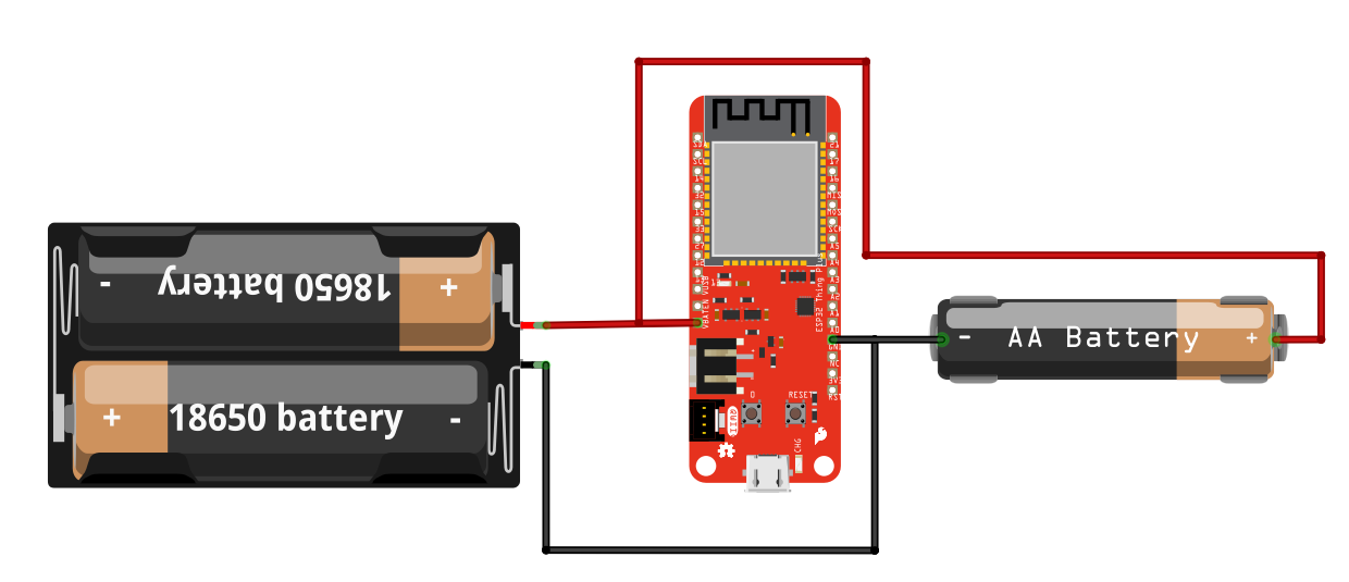
Well, I’ve tried at least 6 different ones and they ALL have this problem. So I kinda wanna fix it, learn how to fix it, or get my hand on one that isn’t messed up
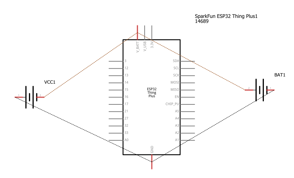
All of @just_randy 's parts look to be incorrect (plus is swapped with - between views.) The desirable solution is for @just_randy to correct them and replace the parts in the post with correct ones. Until that happens, here is a corrected version of the 2 cell version you were asking about and what needs to be done to correct it. This tutorial should give you everything that I am doing here, but part creation in general is quite complex (more so in this case because at least one of the parts has bendable legs which is among the most difficult to deal with!)
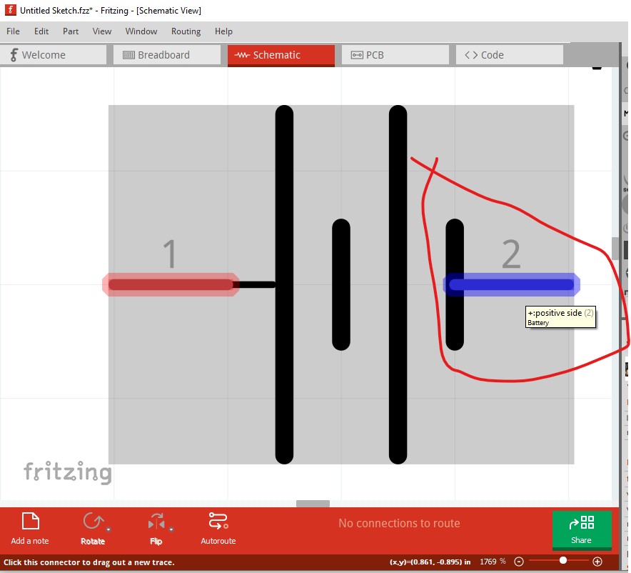
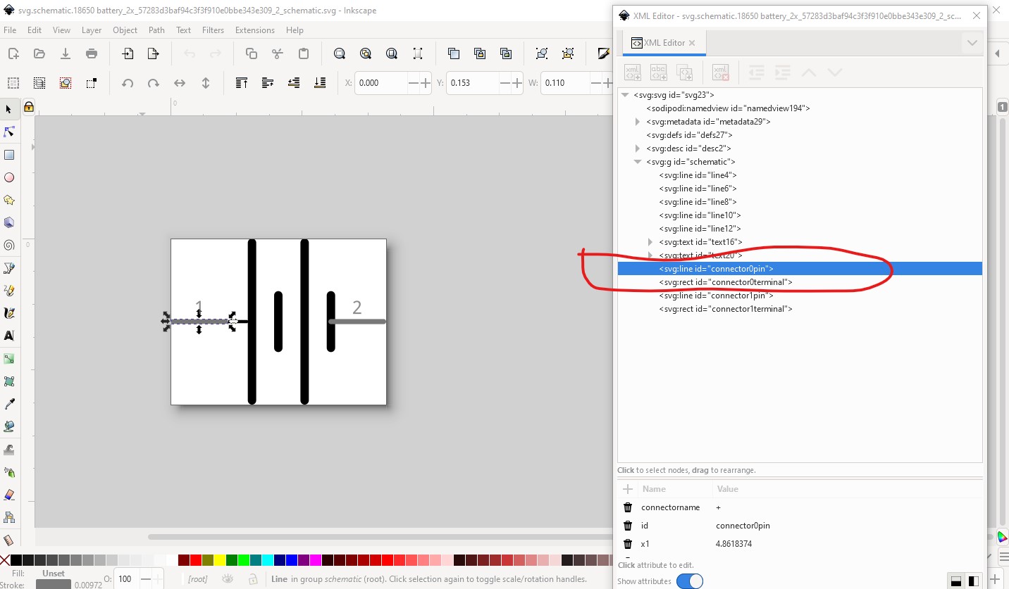
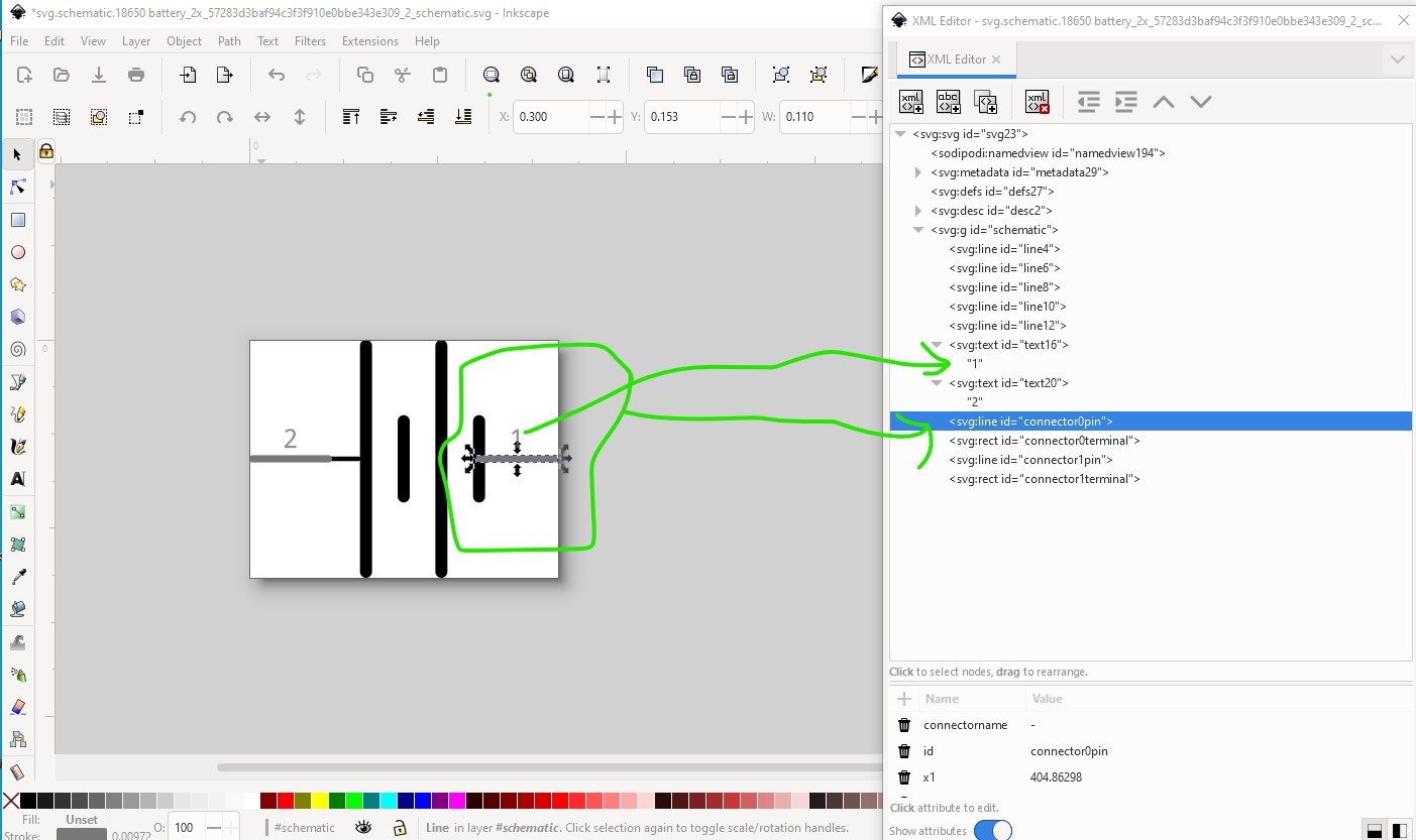
here the negative pin is showing as pin2 (connector1) the positive terminal instead of pin1 (connector0) the negative terminal. That is because the pins are reversed in the schematic svg (displayed here in Inkscape)
where I swapped connector0 for connector1 and changed the pin labels so pin 1 is the negative and pin 2 is the positive. Save this as a plain svg, then rebuild the part and run it through FritzingCheckPart.py to clean it up and remove the px from font sizes and we have a new corrected part.
note you will need to delete the current part from the mine parts bin and restart Fritzing before you will be able to load the fixed part because I didn’t change the moduleId or file names. Hope this helps!