I tried making this part WS2812 8-Bit RGB LED Ring
I took a part from the adafruit library, I took the 12bit neopixel ring and just modified the PCB layer since that all that matters to me, I never use breadboard view and the pinout is the same so changing the schematic view isn’t necessary. The problem I have is I want the pads to be through hole, so I can solder them from the other side of the board, it seems to work and all the dimensions are correct but the solder pads are just Surface mount, but also seem to show up on both sides?
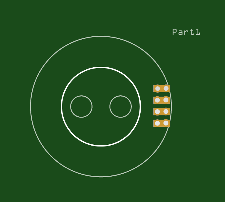
as you can see below it’s not all the way though, I’ll upload my part if someone could help me just even with the PCB view as I said that’s all I need i’d be very grateful.
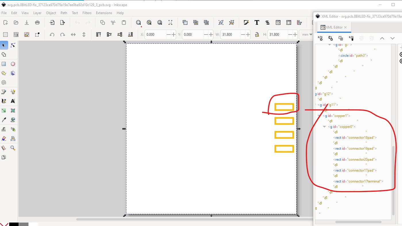
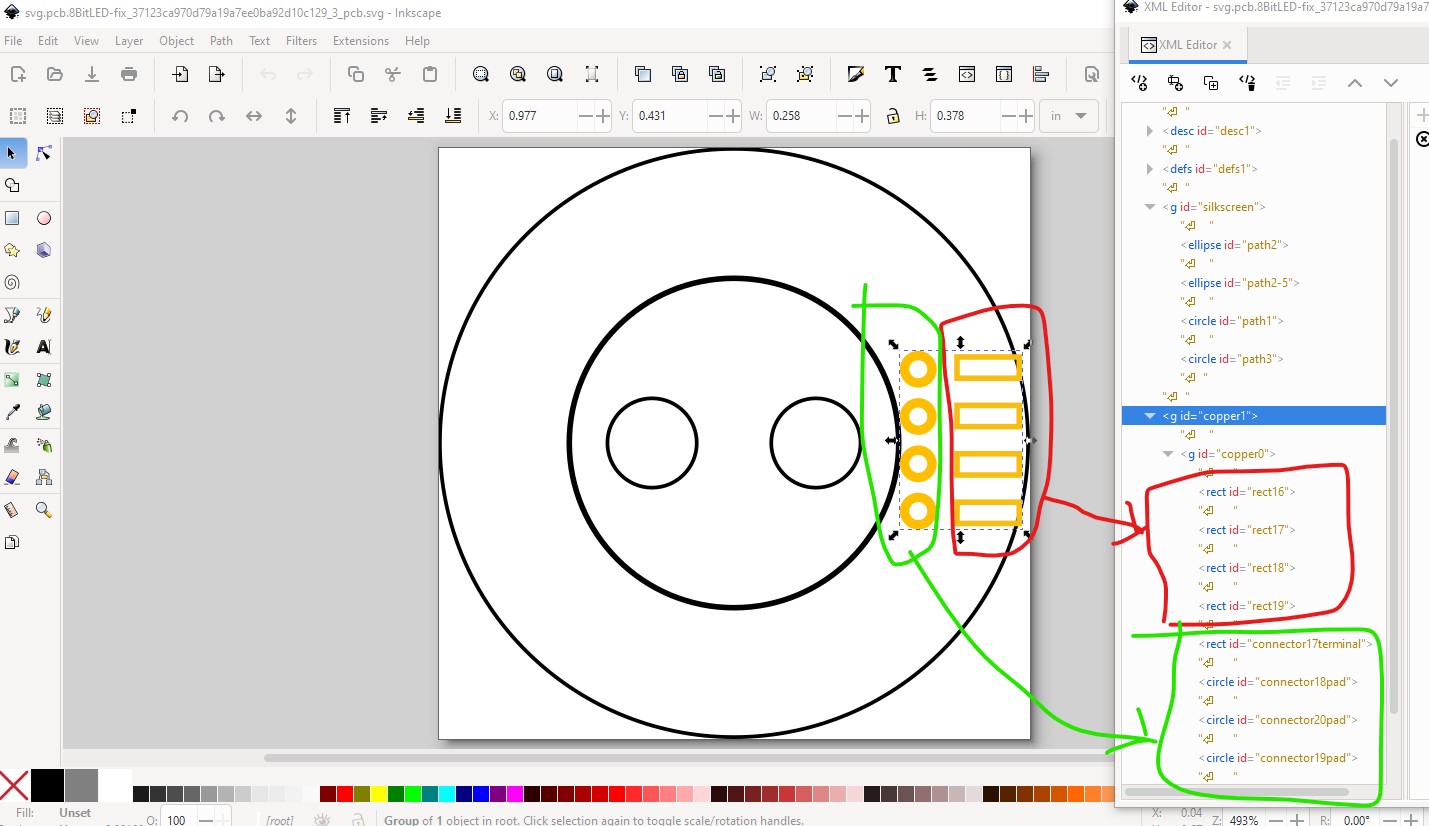
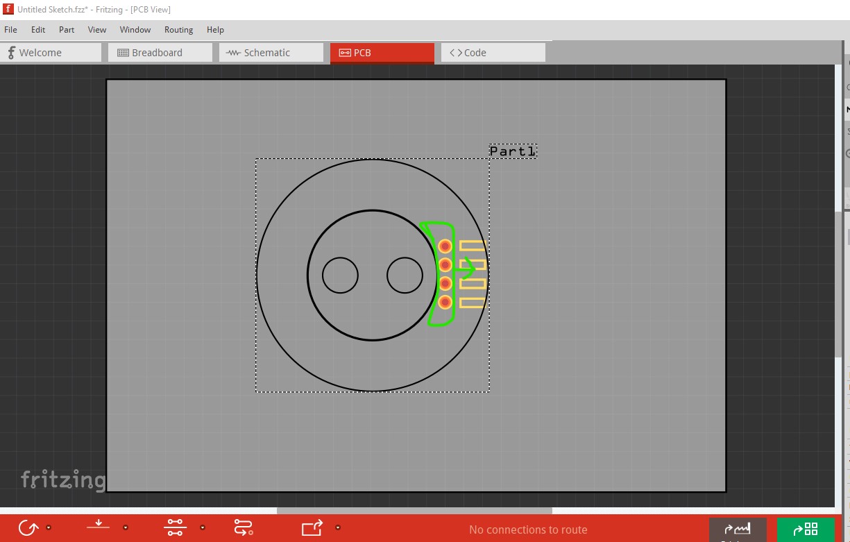
except the pads (circled in green and on 0.1in boundaries) need to move to the appropriate place on the rectangles (circled in red) with the desired pitch and hole size (these are set to 0.038in for 0.1in headers) if it isn’t 0.1in. That produces this as a Fritzing part
Where the pads will be visible through the main PCB and I can solder to the pads on the led ring that way. But it looks like that’s not possible.
Thanks for the help
The problem with that (if you are using a board house) is that the drill overlaps and will often break so many of them will reject such a board. At this time starting apparently with version 0.9.10 it is possible to make parts with slots (although I haven’t yet tried it.) You can get this same effect by putting overlapping pads in the pcb svg (but as noted the board house may reject the gerbers with overlapped holes if the overlap is too great.)
I modified the part so that there’s no overlapping holes, but the square pads I had before connect two separate through holes, So hopefully shouldn’t fail a design check and I can use one of the holes with the soldering iron and feed solder into the other side and should get a decent bond (ideally)