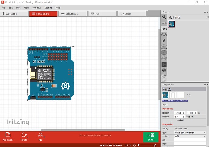
OK, so I unzipped the .fzpz file and ran it through FritzingCheckPart.py which details the problems (I am ignoring a bunch of warnings here that aren’t deadly and only considering errors which imply non functioning.
Error 47: File
‘part.makerfabs_wifi_a7b0ca7379158729b2a45ab7c4a39089_1.fzp.bak’
At line 55
LayerId breadboard doesn’t match View breadboardView layerId breadboardbreadboard
This is likely your main problem. It is this in the .fzp file:
<breadboardView>
  <layers image="breadboard/makerfabs_wifi_9f87ba5baa38121b487ca47bee14d0d2_3_breadboard.svg">
    <layer layerId="breadboardbreadboard"/>
  </layers>
</breadboardView>
the layerId in the breadboardview is breadboardbreadboard but in the connector definitions it is breadboard. The two need to be the same to work.
<connector type="female" name="RST" id="connector0">
  <description>RST</description>
  <views>
    <breadboardView>
      <p svgId="connector0pin" layer="breadboard"/>
    </breadboardView>
    <schematicView>
      <p terminalId="connector0terminal" svgId="connector0pin" layer="schematic"/>
    </schematicView>
here either layer breadboard needs to be breadboardbreadboard or the layer definition needs to change from breadboardbreadboard to breadboard to match the layer in the connectors. I would probably use breadboard for both as it is more standard. That repeats for all the breadboard connectors. Then we hit
Error 69: File
‘svg.breadboard.makerfabs_wifi_9f87ba5baa38121b487ca47bee14d0d2_3_breadboard.svg.bak’
At line 11
Found a drawing element before a layerId (or no layerId)
This indicates you don’t have a breadboardbreadboard layerId in the svg file (it has breadboard instead.) The only consequence of this is that the part won’t expert as an image (which is a problem but not deadly fatal!) Then we have
Error 18: File
‘part.makerfabs_wifi_a7b0ca7379158729b2a45ab7c4a39089_1.fzp.bak’
Connector connector56pin is in the fzp file but not the svg file. (typo?)
svg svg.breadboard.makerfabs_wifi_9f87ba5baa38121b487ca47bee14d0d2_3_breadboard.svg.bak
which indicates connector56 is in the fap file but not in the svg which will cause problems. fzp file entry:
<connector type="female" name="GND" id="connector57">
  <description>GND</description>
  <views>
    <breadboardView>
      <p svgId="connector57pin" layer="breadboardbreadboard"/>
    </breadboardView>
    <schematicView>
      <p terminalId="connector57terminal" svgId="connector57pin" layer="schematic"/>
    </schematicView>
    <pcbView>
      <p svgId="connector57pad" layer="copper1"/>
      <p svgId="connector57pad" layer="copper0"/>
    </pcbView>
  </views>
(which has the original breadboardbreadboard layerId)
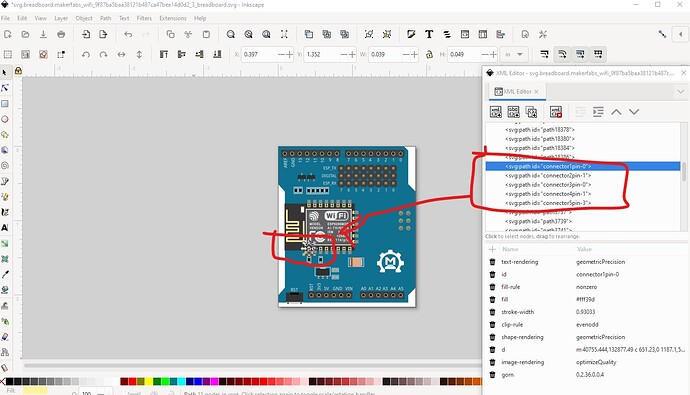
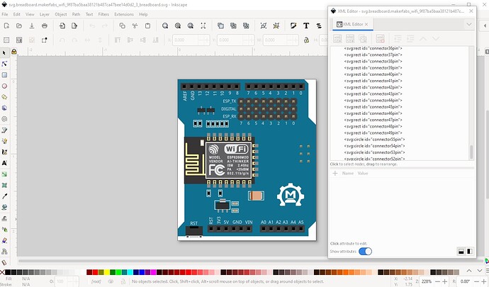
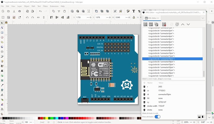
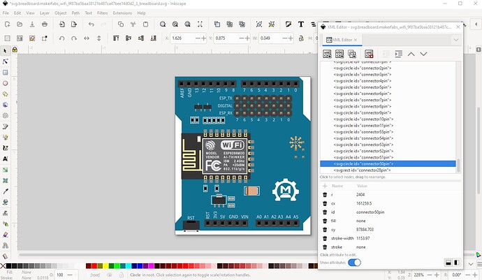
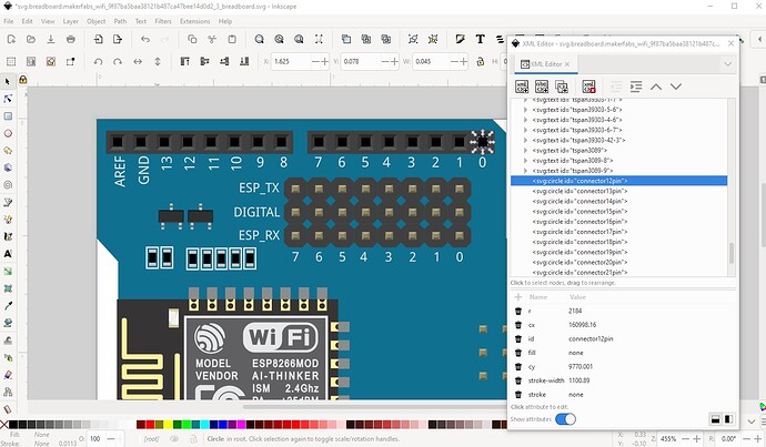
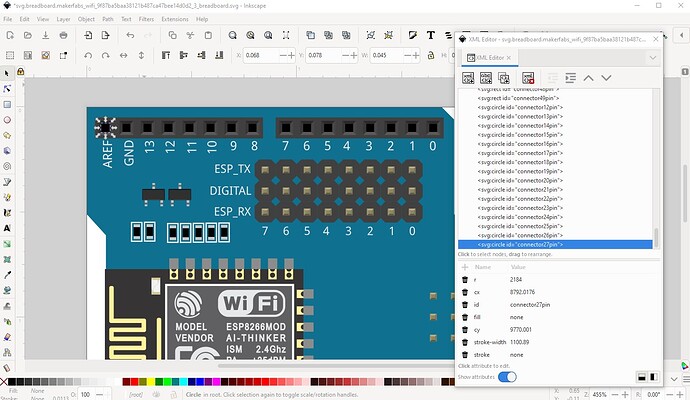
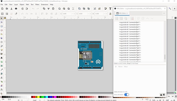
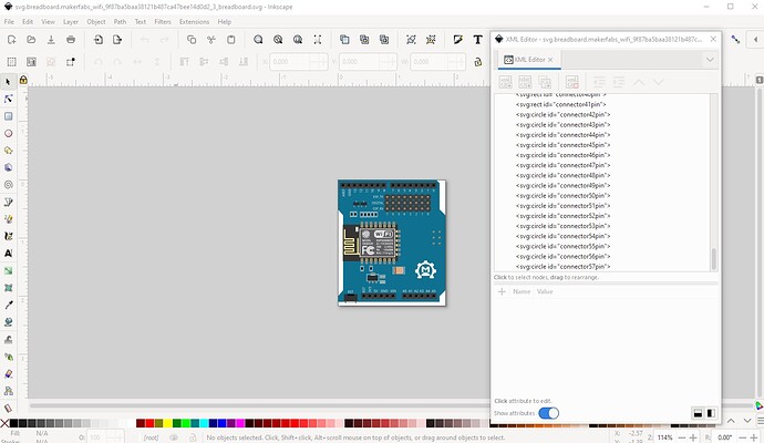
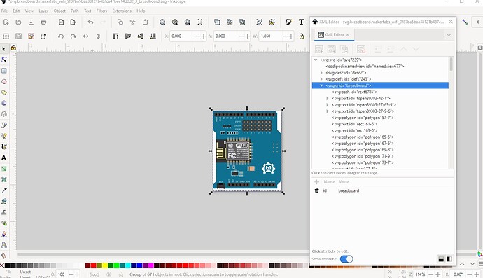
but the svg has no connector57 defined. This will cause a red rectangle (indicating missing connectors) in the Fritzing breadboard display. So I edited the breadboard svg in Inkscape and ungrouped it, them moved the connectors in pin order to the bottom of the svg. Once that was done I searched for “connector” which turns up this:
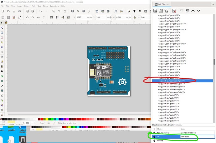
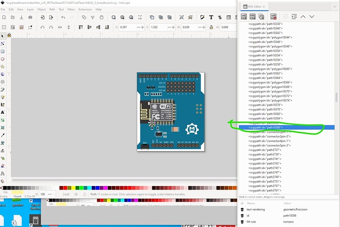
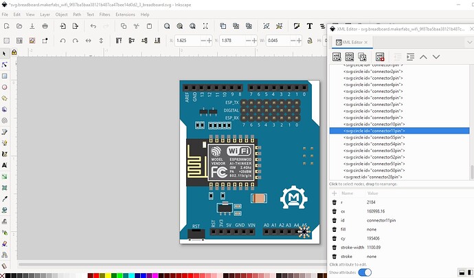
there are 5 connectors here that are not used. To avoid problems (which won’t occur if they aren’t defined in the fzp file as they are not) I replaced the id with a path like this
as noted this isn’t required but is useful as there aren’t any connectors that are not real connectors any more.
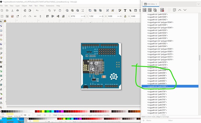
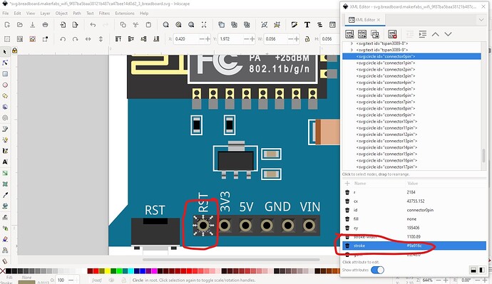
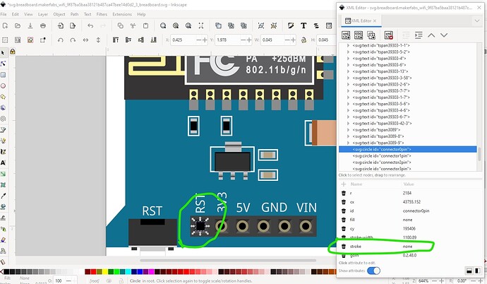
now I move to connector0 where moving it to the bottom has broken the image as the connector has a stroke value. There are two ways to fix this, in Inkscape just replace the stroke with none like this:
then repeat for the rest of the pins or save the svg then edit it with a text editor (vi in this case) and do a global replace of the stroke value with none like this:
 <circle
     gorn="0.2.48.0"
     stroke="none"
     stroke-width="1100.89"
     cy="195406"
     fill="none"
     id="connector0pin"
     cx="43755.152"
     r="2184" />
  <circle
     gorn="0.2.48.1"
     stroke="#9a916c"
     stroke-width="1100.89"
     cy="195406"
     fill="none"
     id="connector1pin"
     cx="53524.152"
     r="2184" />
:.,$s/stroke=“#9a916c”/stroke=“none”
which will change all the stroke=“#9a916c” to “none” and do all the changes at once. Now with that done:
I am going to change the order of the pins (and then renumber them!) in to a format suitable for the schematic extension documented here:
basically the bottom 12 pins will be on the bottom, the 6 ICSP pins and the 24 esp pins will be on the right side and the 16 top pins will be on the top like this:
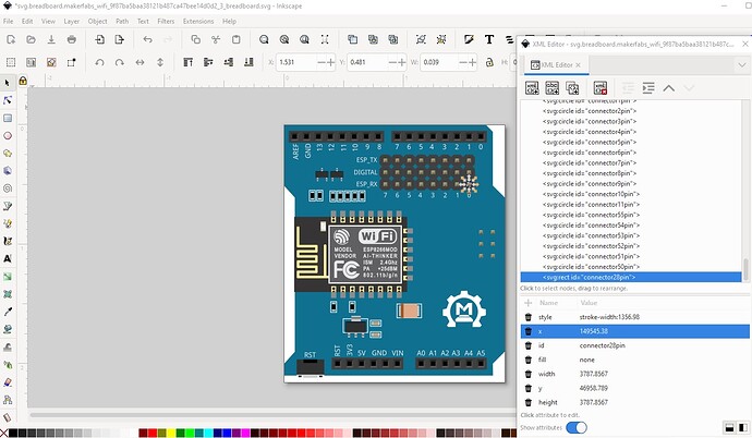
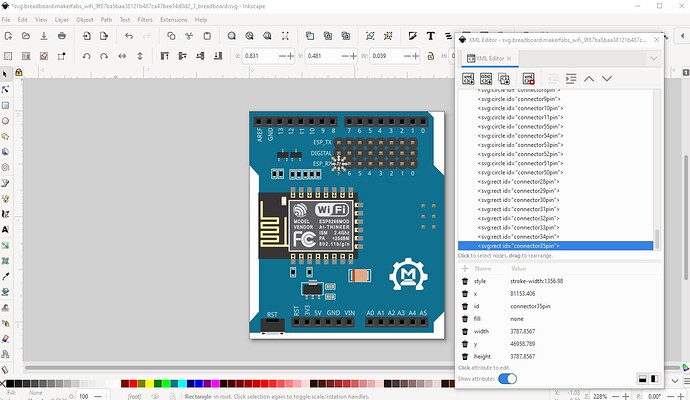
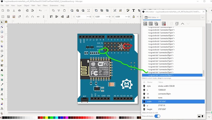
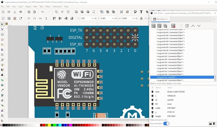
here a problem appears, we are missing two connectors on the header. It jumps over 2 pins from connector35 to connector36, so we need to define connectors for the two missing pins. To do that I select the rectangle that is the connector (it has no fill!) on the pin and move it after connector35 like this:
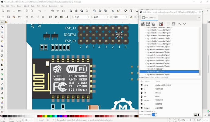
then do the same for the next pin along like this
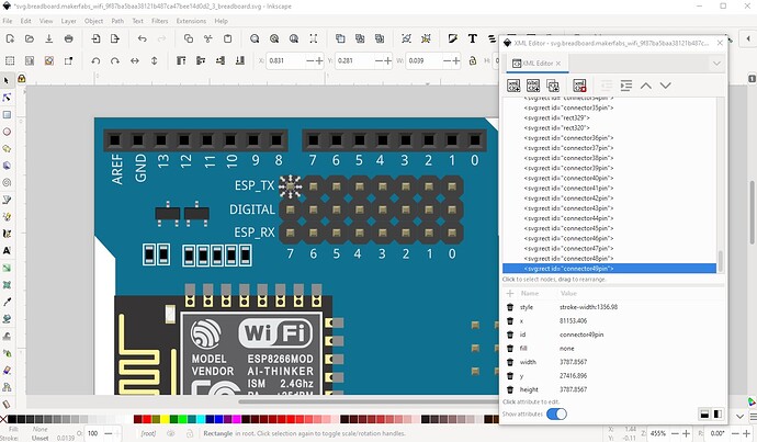
now proceed moving the pins to the bottom in order
then do the top row
Now we are finished with the connectors in the correct order (if not numbered correctly) so now I save the svg, then run a script to renumber the pins. Connector0pin is the correct starting point and it will renumber from there like this (you can also do this manually by updating each id in Inkscape but that s tedious and error prone!)
$ setbb.py svg.breadboard.makerfabs_wifi_9f87ba5baa38121b487ca47bee14d0d2_3_breadboard.svg
*** Process svg.breadboard.makerfabs_wifi_9f87ba5baa38121b487ca47bee14d0d2_3_breadboard.svg ***
which results in
where the connectors start at connector0 and go to connector57 (for 58 connectors.) Now we are ready to set the layerId to breadboard like this:
then save the completed breadboard svg.
Now we need to modify the fzp file to match the new breadboard svg. First we correct the layerId from
to
to match the layerId in the breadboard svg. Then I deleted all the connector definitions (I also need to delete the bus definitions below it later!) from this
  <connectors>
    <connector type="female" name="RST" id="connector0">
      <description>RST</description>
      <views>
        <breadboardView>
          <p svgId="connector0pin" layer="breadboard"/>
        </breadboardView>
        <schematicView>
          <p terminalId="connector0terminal" svgId="connector0pin" layer="schematic"/>
        </schematicView>
        <pcbView>
          <p svgId="connector0pad" layer="copper1"/>
          <p svgId="connector0pad" layer="copper0"/>
        </pcbView>
      </views>
    </connector>
    <connector type="female" name="3V3" id="connector1">
      <description>3V3</description>
      <views>
        <breadboardView>
…
to this
  <connectors>
  </connectors>
  <buses>
    <bus id="+5v">
      <nodeMember connectorId="connector40"/>
      <nodeMember connectorId="connector87"/>
    </bus>
    <bus id="gnd">
      <nodeMember connectorId="connector44"/>
      <nodeMember connectorId="connector57"/>
      <nodeMember connectorId="connector88"/>
      <nodeMember connectorId="connector89"/>
    </bus>
    <bus id="reset">
      <nodeMember connectorId="connector43"/>
      <nodeMember connectorId="connector85"/>
    </bus>
  </buses>
</module>
then generated a new connector set of 58 connectors like this:
$ cons.py -n t 58
which creates this with pin numbers but blank descriptions
  <connector id="connector0" type="male" name="Pin 1">
    <description></description>
    <views>
      <breadboardView>
        <p svgId="connector0pin" layer="breadboard"/>
      </breadboardView>
      <schematicView>
        <p svgId="connector0pin" layer="schematic" terminalId="connector0terminal"/>
      </schematicView>
      <pcbView>
        <p svgId="connector0pin" layer="copper0"/>
        <p svgId="connector0pin" layer="copper1"/>
      </pcbView>
    </views>
  </connector>
  <connector id="connector1" type="male" name="Pin 2">
    <description></description>
    <views>
      <breadboardView>
        <p svgId="connector1pin" layer="breadboard"/>
      </breadboardView>
      <schematicView>
now I copy the file in to the .fzp file like this
<connectors>
  <connector id="connector0" type="male" name="Pin 1">
    <description></description>
    <views>
      <breadboardView>
        <p svgId="connector0pin" layer="breadboard"/>
      </breadboardView>
      <schematicView>
        <p svgId="connector0pin" layer="schematic" terminalId="connector0terminal"/>
      </schematicView>
      <pcbView>
        <p svgId="connector0pin" layer="copper0"/>
        <p svgId="connector0pin" layer="copper1"/>
      </pcbView>
    </views>
  </connector>
  <connector id="connector1" type="male" name="Pin 2">
    <description></description>
  ...
        <p svgId="connector56pin" layer="copper0"/>
        <p svgId="connector56pin" layer="copper1"/>
      </pcbView>
    </views>
  </connector>
  <connector id="connector57" type="male" name="Pin 58">
    <description></description>
    <views>
      <breadboardView>
        <p svgId="connector57pin" layer="breadboard"/>
      </breadboardView>
      <schematicView>
        <p svgId="connector57pin" layer="schematic" terminalId="connector57terminal"/>
      </schematicView>
      <pcbView>
        <p svgId="connector57pin" layer="copper0"/>
        <p svgId="connector57pin" layer="copper1"/>
      </pcbView>
    </views>
  </connector>
</connectors>
<buses>
Now I need to add the description fields from the breadboard svg like this:
  <connector id="connector0" type="male" name="Pin 1">
    <description>RST</description>
    <views>
as they won’t affect functionality I’ll only do connector0. Because the current bus definitions also won’t affect functionality I will ignore them as well. Now running FritzingCheckPart.py
$ FritzingCheckPartw.py part.makerfabs_wifi_a7b0ca7379158729b2a45ab7c4a39089_1.fzp
complains about missing bus members
Error 53: File
‘part.makerfabs_wifi_a7b0ca7379158729b2a45ab7c4a39089_1.fzp.bak’
At line 925
Bus nodeMember connector87 does’t exist
Error 53: File
‘part.makerfabs_wifi_a7b0ca7379158729b2a45ab7c4a39089_1.fzp.bak’
At line 930
Bus nodeMember connector88 does’t exist
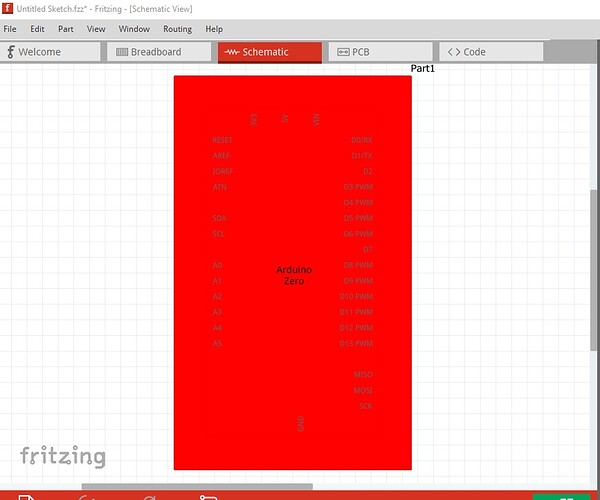
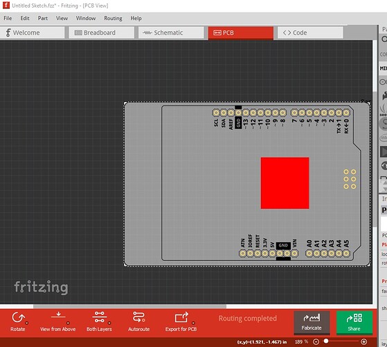
but doesn’t bitch about breadboard only schematic and pcb (neither of which are corrected yet!) so we should be able to make a part that runs in breadboard correctly like this:
although schematic and pcb do not (yet!)
technically (and practically) breadboard is not correct because the fzp file needs the ICSP and ESP pins defined as female like this (which I haven’t done!)
from this
<connector id="connector12" type="male" name="Pin 13">
  <description/>
  <views>
    <breadboardView>
to this
<connector id="connector12" type="female" name="Pin 13">
  <description/>
  <views>
    <breadboardView>
the change from male to female means the pin won’t connect to the breadboard (where it would short!) as the breadboard pins are female. As noted the next step is to create the schematic svg using the Inkscape extension and then pcb (the easy way is to copy breadboard then delete the uneeded parts which is everything except the connectors, board outline and mounting holes) and apply the correct groups. I can do that if you like. Here is the part created above with the working breadboard and fzp files.
Makerfabs WiFi Shield-fixed-breadboard.fzpz (71.8 KB)
Peter
