I’m new to Fritzing and followed Appideas Instructable: “Custom PCBs on a CNC Router”. I placed holes as per the instructions, but when I Export for PCB, the drill.txt file is missing?
The holes show on the silkscreen layers, I must be missing a step to tell Fritzing I want them to go through all layers of the PCB?
The likely answer is that the pads are ellipses which don’t create holes in gerber post processing but look fine in pcb view. If you upload the .fzz file of your sketch (upload is 7th icon from the left in the reply menu) I will have a look.
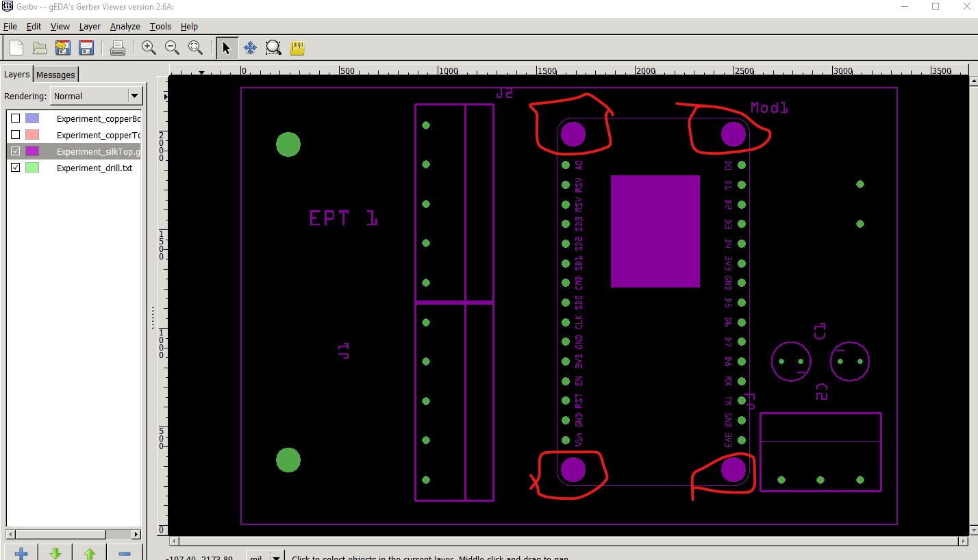
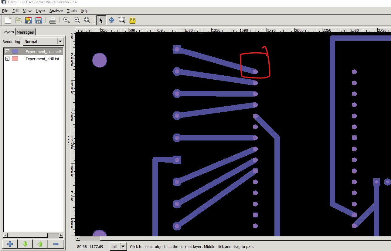
Everything looks pretty much as expected. The 4 mounting holes circled in red on the last image are not set to be drilled. If you want them drilled you need to drag a hole in to pcb and set the size correctly then place it over the hole in silkscreen. This is on Fritzing 0.9.10 on Win10. What Fritzing version and OS are you using?
The two holes on the left side of the image you attached are the two I was expecting to be drilled. I now realize the ESP8266 needs those other four drilled.
Did Export for PCB produce a drill.txt file for you? If so, then maybe it is a problem with my system or the download?
If your install isn’t doing so then there is something wrong. A reinstall may fix it I expect I haven’t heard of any problems with 0.9.10 on the Mac (and a check of issues on github doesn’t show anything.)
There is a problem with the cpu part though. It has no pads on the pcb so you will only get holes (indicated by this in the drill.txt file)
; NON-PLATED HOLES START AT T1
; THROUGH (PLATED) HOLES START AT T100
M48
INCH
T1C0.044000
T100C0.040000
T101C0.027559
T102C0.125984
%
T1
X025421Y009297
X016483Y018259
X025421Y012285
X016483Y014276
X016483Y012285
…
The T1 indicates a non plated through hole which is why it is hole only (the holes are also too big at 0.044in they should be 0.038 for 0.1in headers.) I’ll correct the part and post it in a bit. Here is the hole problem note no pad around the hole.
edit: well that was easy I apparently already did this in this post
Amica NodeMCU DevKit 1.0-improved.fzpz from that post is the corrected part (it still needs the mounting holes replaced by holes though.) If you use “delete minus” to delete the part that will leave the traces connected. When you replace the part you then need to click on the end of the trace and drag it on to the pad on the part to remake the connections (unfortunately in all three views though.) I sometimes find it easier to just redo the traces.