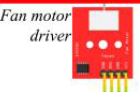
Pls Help me find this componen, i need this type of fan motor driver
Pls Help me find this componen, i need this type of fan motor driver
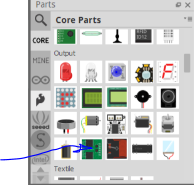
We would need a web site for what you want. I’d guess it is probably this
but the site for what you have would be needed to find or make a part.
Peter
That’s an awesome H-Bridge! 
hi peter,
is this h-bridge 100% functional on all 13(!) connections?
so long
pc
Assuming you are referring to the l298n part there are 17 connections and they are all functional.
Peter
super ! … 17? (but with jumpers)
Yes, both the 5V enable and the two 5V power pullups are intended to be jumpers but need to be connectors in Fritzing.
Peter
well done !
pushbutton works, too …
thanks very much …
My students use this part a lot and I would like to put it as a core part. However, to keep cleaning the core parts, I think there are necessary a couple of small improvements.
Thoughts?
If we make these changes, do we need to obsolete the parts?
My changes were made before we moved to A for assembly, so that is trivial to change and should be changed.
I tend to use very specific to the module family names so there is little chance they will conflict with a core part. I agree that we need a better standard for family names, @microMerlin likely has opinions on this topic too ![]() , I think he prefers the rather non specific so you can choose a part based on a family name. I suspect the correct answer is to start a discussion on how we would like to see the family standardized and then write that standard (which as far as I know hasn’t happened yet.) Until that discussion is settled I have no problem with naming them both H-bridge motor driver with the variant being the model of the part. Again easy to do and easy to change if we manage to come up with a standard it doesn’t meet.
, I think he prefers the rather non specific so you can choose a part based on a family name. I suspect the correct answer is to start a discussion on how we would like to see the family standardized and then write that standard (which as far as I know hasn’t happened yet.) Until that discussion is settled I have no problem with naming them both H-bridge motor driver with the variant being the model of the part. Again easy to do and easy to change if we manage to come up with a standard it doesn’t meet.
Yes. This board is entirely screw terminals. The idea is the pins are outside the board so you solder wires in to the pads and run the wire to the screw terminals on the module (as that is the only way to connect to it.) It just isn’t specified anywhere but maybe in the forum post (and maybe not anywhere ![]() )
)
They can and should be removed assuming I can figure out which of the html markups are doing them (I’m not particularly html literate ![]() )
)
A search for MD03A1 in core parts on 0.9.10 isn’t coming up with anything, I’ll try a broader search and see what appears. A search for motor driver doesn’t show anything either (other than a lot of motor drivers that should be probably combined in to one family.) Do you have a search term that will bring it up in core parts on 0.9.10 or have you possibly loaded an external part that is being found? If it isn’t in core parts it shouldn’t need obsoleting.
We also at some point need to sort out and document obsoleting. The current requirements are I think broken, just changing the view box size appears to be able to break obsoleting as I recall from a previous go around trying to obsolete something.
Peter
Done ‘correctly’, I see this as expanding on, instead of conflicting with. I believe that Inspector will allow switching between core and custom parts that have the same family name. As long as there are matching property names with unique values.
![]() Yes
Yes
I can help with that. I don’t do a lot of html, but it is in the skill set. Whitespace is straight forward once some basic concepts are understood. About where things are collapsed to a single space, or kept as is. This mixes with css, which might not be understood by people getting started.
For this, I believe you mean the feature that allows replacing an obsolete part in a sketch with it’s new version? Yes, the interactions are very unclear. I strongly suspect that (a large part of) the real problem is in the code. Documenting what the current limitations are is a start, but it should be possible to handle a lot more cases than currently work as expected.
AFAIK this is correct with the limitation (which I think is a bug) that unless you save the part in the bin Inspector doesn’t recognize it. Just loading the part, Inspector doesn’t allow you to change (the parameters are greyed out.) Closing Fritzing and saving the bin fixes that and then it works as expected I think.
I think this is true, but seems to have a low (perhaps justifiably) priority with the developers. I expect parts editor improvements and urgent bug fixes are taking all available time. Since there aren’t many new parts submissions it is hard to argue against the low priority.
Peter
OK here is an updated copy of the part. Label changed to “A”, family “H-bridge motor driver” variant “variant L298-Module” and the description replaced with a shorter text version (which avoided me figuring out the html ![]() .) I don’t know where the other motor driver is to change that.
.) I don’t know where the other motor driver is to change that.
L298N-DC-motor-driver-further-improved.fzpz (27.9 KB)
Peter
Great @vanepp !
The other motor controller is the core bin:
It is the MD03A.
There are also other H-bridges in Fritzing:
h-bridge.fzp which is in the IC family!
The Motor controller family:
MonsterMoto-Shield-v12.fzp:Motor Controller
quadstep-v12.fzp:Motor Controller
And the motor driver family:
grep -ri “>motor driver</p”
A4950_37.fzp: motor driver
Dual_VNH2SP30_Motor_Driver.fzp: Motor Driver
EasyDriver_v44.fzp:Motor Driver
FRM050.fzp: Motor Driver
L293D.fzp: Motor Driver
Rotoshield-1.0a.fzp:Motor Driver
I would only make minor adjustments in these fpz files unless these parts have critical issues. Basically, changing the family, label and variant. If we need to change the svg files, we need to obsolete them, which takes much more time.
I must be getting blind! Now when I enter MD03A in the search box it comes up, when before it didn’t (or I mistyped the part number ![]() .) A quick looks says it needs svg changes, the pin numbering starts at 130 (perhaps created from eagle2fritzing?) and should be converted to start at 0. The svgs may not meet the graphics standards either but I haven’t yet looked closely. I’ll have a closer look at what needs doing to clean it up.
.) A quick looks says it needs svg changes, the pin numbering starts at 130 (perhaps created from eagle2fritzing?) and should be converted to start at 0. The svgs may not meet the graphics standards either but I haven’t yet looked closely. I’ll have a closer look at what needs doing to clean it up.
Peter
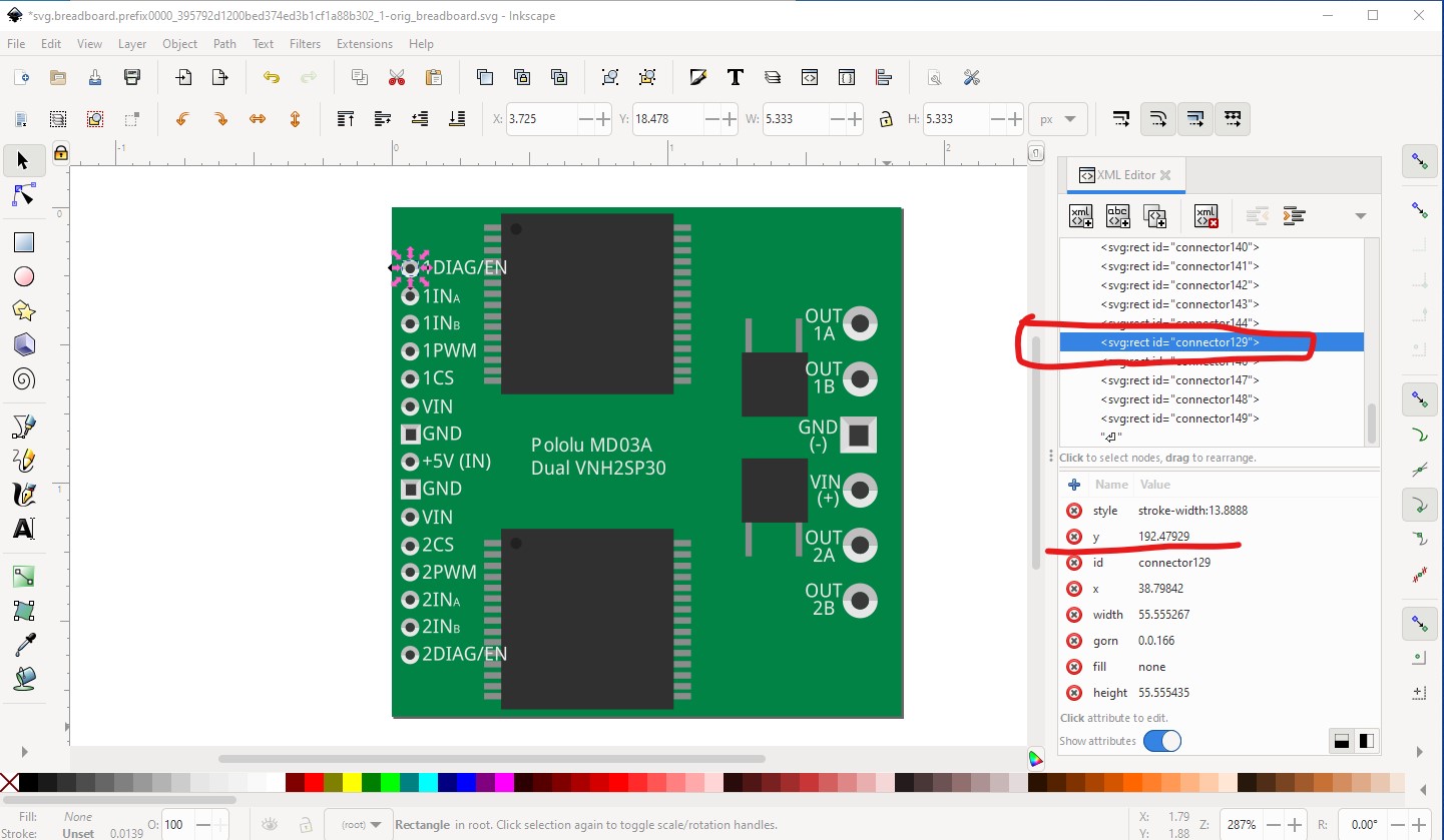
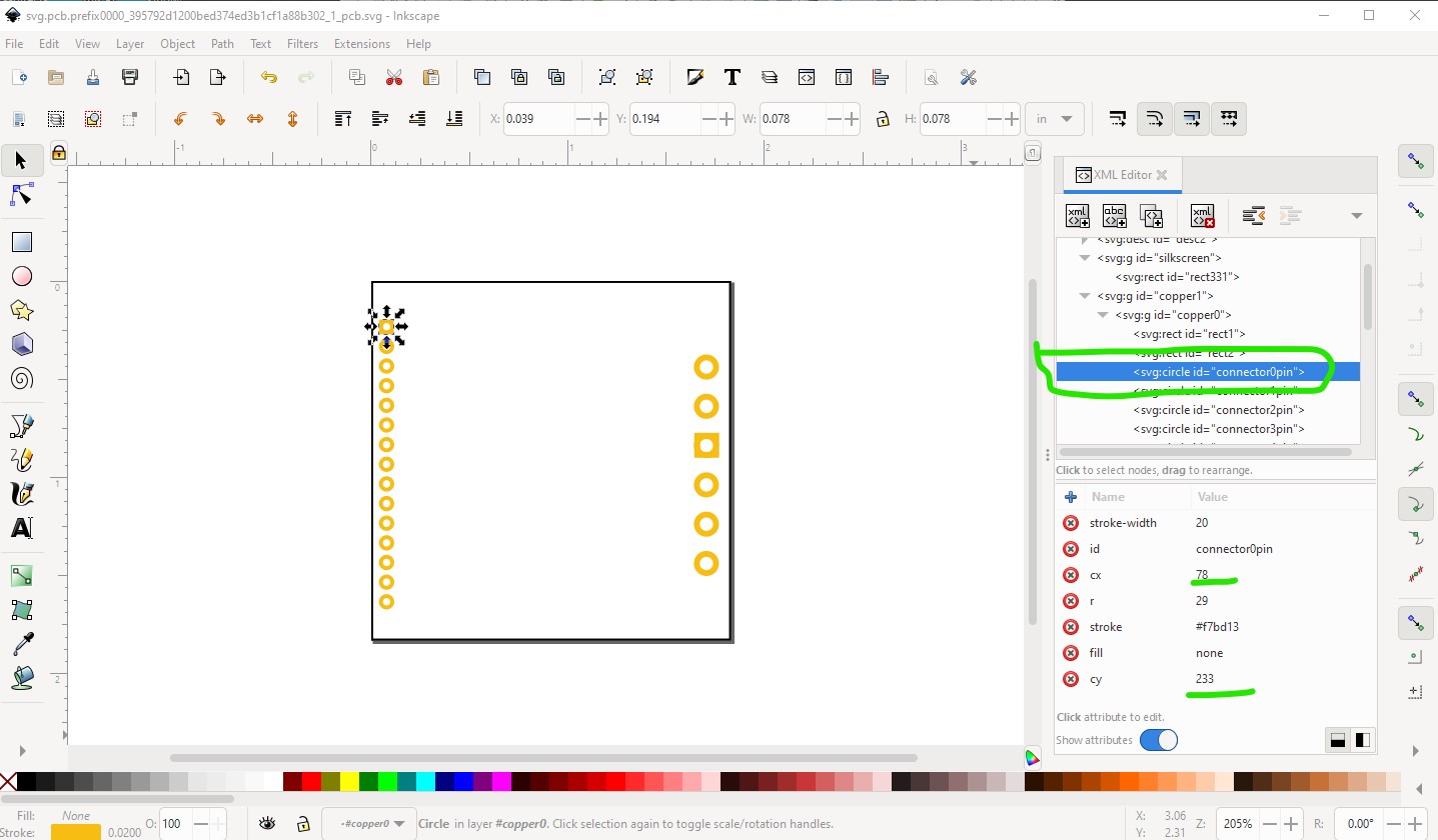
OK here is a trial part for the MD03A part. It is a trial part because it currently requires obsoleting because the pin numbering has changed. I’m willing to try and figure out obsoleting and see what happens (i.e. how successful the upgrade is.) as well there are options for schematic other than the one I have chosen, a different one may suit your purpose better. The original bb is not that bad, the major problem is the pins start at 129 and go up. They should start at 0 but that will require obsoleting the part to change the pin numbers (which I am in favor of!) For comparison purposes I rescaled the svg to the correct scale so 1 drawing unit is 1/1000in this is the original svg
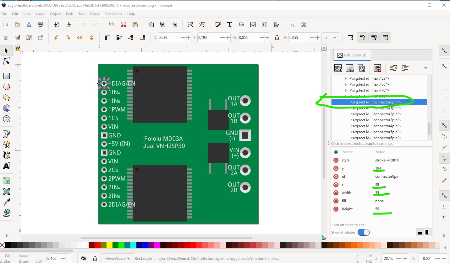
Of note here is the first pin is connector129pin (and is out of sequence!) and the coordinates in xml editor have digits after the decimal sign (less that 1/1000 of an inch!) which are not useful and should be rounded for better clarity (at least in my opinion!) Then I rescaled the svg to be correct (1 drawing unit = 1/1000inch) and cleaned up the alignment of the pads and text. While doing that I rounded the numbers in the xml to 1/1000 of an inch (we don’t need more than that and it can be automated by a script with some work for exceptions that need more precision.) I also renumbered the pins to start at 0 and increase sequentially (unlike the original!)
This has the effect of aligning the pins on exactly (within 1/1000 of an inch) to the 0.1inch grid.I also converted the strings that were individual characters in to strings which makes them easier to modify (as well as the svg slightly smaller.) The major change is the pin numbers starting from 0 instead of 129. This will require the part to be obsoleted to adjust the pin number mapping (which I am in favor of doing so we don’t have to visit this part again later!)
On to schematic
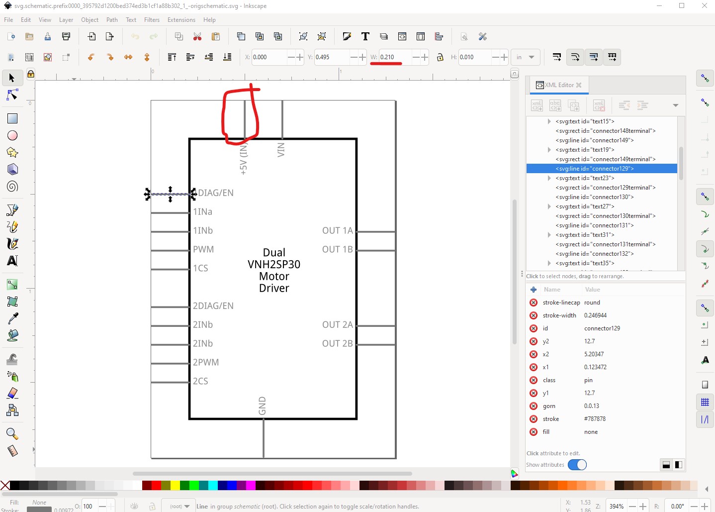
This is the original schematic, again the major change is pin numbering, but there are a few more issues. The pins are 0.2in long rather than the preferred 0.1in and the colors don’t conform to the graphics standards.
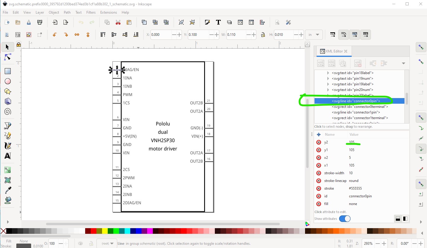
I chose to use Randy’s schematic Inkscape extension to make a new schematic in my favored format:
The pins are renumbered to start at connector0 and the xml numbers are rounded to 1/1000 of an inch. The overall layout mirrors breadboard (which I find more useful when debugging, but others may not like!) That means there are no pins such as ground overlaid to create one connection. The downside to this is that Fritzing will not let you make a connection to a ground pin if there is already a connection to the ground net somewhere else in the same net. That can be confusing to a new user and I believe is the main reason for using overlaid pins. I like this because if I am debugging on the actual board the schematic pin is in the same position it physically is on the board which makes it easy to find in schematic. We could chose to move all the ground pins to the bottom and all the power pins (overlaid to give a single connection point) on the top if that would suit better. If we leave the pin numbers as is (starting at 129) we can avoid doing the obsoleting, but as noted I would prefer to renumber the pins. I can have a look at figuring out how to do that if you like.
on to pcb
Mostly more of the same, rescaled, renumbered to start at connector0pin with the numbers rounded to 1/1000 inch. In a number of cases I changed the pins from paths to circles as circles are easier to change (and get a consistant hole size from!) than paths.
on to the fzp
add version tag set the version to 2 (assuming the original was version 1!)
update the Fritzing version to 0.9.10
add my name to author
change label from MD03A to A (for assembly)
change family from “motor driver” to “H-bridge motor driver”
change varant from “variant 2” to “variant MD03A”
moved the url from the decription to the field
added missing silkscreen layerId to the pcb layers.
renumbered the pins with standard boiler plate connectors, copy the descriptions from the original as the original has incorrect svgIds!
add buses which are missing in the original part! That results in this test part which has all of these changes. See if you would prefer a different schemematic layout.
Dual_VNH2SP30_Motor_Driver.fzpz (11.9 KB)
Peter
Hi @vanepp ,
we can obsolete the part if it is necessary. In this case, we do not have to reuse the svgs in other files, and maybe we can use Fritzing´s script: fritzing-parts/obsolete.py at develop · fritzing/fritzing-parts · GitHub It has some limitations (obsoletes all svgs and other issues), see discussion here, but it may not be an issue for this part.
Regarding the schematic symbol, I prefer the original one. Schematic symbols should be grouped by functionality rather than their position in the physical package. This makes them easier to understand and to route. See for example KiCad guidelines section S4.2.
Regarding stacking ground and power connections, I think we may not need to do it. If they are all visible, it is easier to understand that several of them exist and we avoid issues with Fritzing. It definitely should be easy to use for new users.
OK here is a new version of the part with a schematic modified back to the original. The power pins are set on top and bottom as recommended by Kicad but are overlaid on one another because if we are going with schematic as an abstract view that is more correct. The pins that are over laid have their stroke (except for the 1st occurrence) set to none so they are invisible (leaving the stroke set makes the pin bolder when rendered.) I think this is one of the things that should be standardized, what exactly a schematic in core parts should look like (obviously with external parts schematic can be whatever the poster wants, the only place we really have control is core parts. I expect @KjellM and @microMerlin will want to comment, but any one else that has an opinion is also welcome to chip in. I know in the past (when the forums had many more participants!) this was a contentious issue with a number of folks not wanting any standard applied. I suspect (as I did then) having standards for core parts is desirable for a variety of reasons, mostly consistency so when people clone a part they start from a part that is properly configured. This currently is not the case in core parts, but eventually I hope to clean that up but first we have to agree on a standard which may not be easy.
Dual_VNH2SP30_Motor_Driver.fzpz (8.8 KB)
Peter
Given the current code constraints, your description matches my preferences. If the code worked better with buses, combined with excluded pins in the schematic view, that would seem the way to go. Visually (and electronically) it would give the same result.
Then maybe that is what to hope/ lobby for. Cleaning up core parts is going to take a long time, so code changes have time to come to the rescue. If work is being done on buses, I would like to see the restriction of only schematic subparts or buses not both removed. I don’t see why the restriction is there now, I assume a shared data structure of some kind.
Peter