I needed it for senior design so now you can use it! I didn’t really know how to design the PCB part so I’m sorry about that.
On the side note creating this was one of the most frustrating things I’ve ever done. Why is it that text doesn’t work properly unless you remove the PX from the text code! and then even when you do that it doesn’t work properly, I was smashing head against the wall trying to make the schematic.
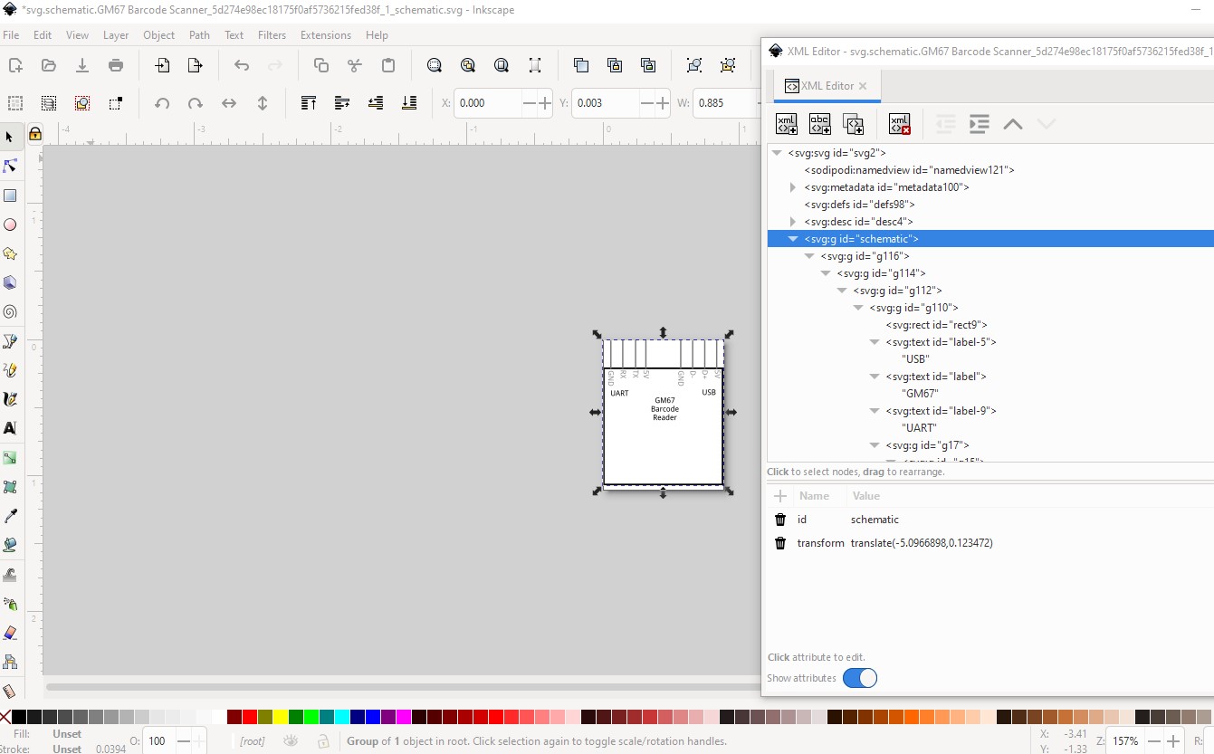
That is a difference between Fritzing (which doesn’t like the px on font sizes and will screw up the font size) and CSS compliance (which requires the px on font sizes.) I have wondered (but not done anything about) if Fritzing couldn’t be changed to remove the px on svg import, but that may not be possible as I suspect it is an issue in QT (the graphic package Fritzing uses) rather than the Fritzing code. I usually avoid this by running the part through FritzingCheckPart.py which will remove the px from font-size (among other things.) For schematic, you are lacking a layerId and thus you part won’t export as an image (schematic will be missing.) To fix that change this group id to schematic
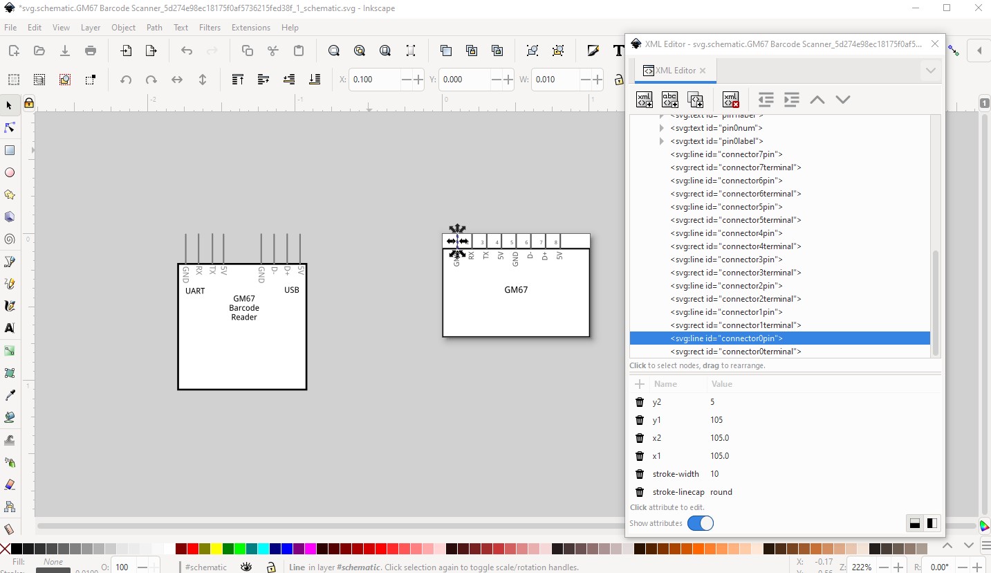
which is part of my parts making tutorial series. It creates a properly formated schematic like this from tabular input and text. It does require that you use Inkscape which may be an issue though. In your current schematic the pins are too long (they should be 0.1in high) and not on 0.1in boundaries
here orig is your original schematic svg (rescaled to the same scale the extension uses which is the preferred 1 drawing unit = 1/1000in.) Then I typed in the pin names in pin order and hit finished. Which creates this (after moving orig left so the two don’t overlap!) Note because the pins are on the top I needed to set the pins from sequential to user defined to get them in the correct order.
Thanks for the help. It still seems that I was missing a few things thanks for the help. On the other hand, I was trying to find a way to easily connect wires to a bcb by using some sort of plug like a UART for the barcode scanner and something else for the RFID reader. Online information seems to scarce on this topic.
I’m not real clear on what you are asking here. It you are looking to add a connector to a pcb that will connect to the barcode reader via a cable, you need to find (or make) a suitable socket part and include that in the pcb. If you are trying to make the cable that connects the barcode reader to another board, that is possible (but somewhat complicated) to do. I did one some years ago that is posted in the forums somewhere.