Github fritzing-parts Critical Issue #416

This is version 1.0.5

This is version 0.9.10

As well in schematic the wire terminates to the centre of the pin

Fixed part:

edit(@vanepp) June 6 2025

replace the part with an updated fix. If you have loaded this you will need to delete the part from your mine parts bin and then shutdown Fritzing (answering yes to keep parts and keep parts bin) to really delete it. When Fritzing restarts you should he able to load the new part.

7-SEGMENT-DISPLAY1-fixed.fzpz (7.8 KB)

The images don’t show, probably because they are links to a private github repo?

Ah, I’ll update them

@KjellM The issue came from here

Oh dear, it is more complicated as I expected. Anyway a log on what I’ve done

Undefined Connectors - solved]


Schematic with missing terminalIDs – solved.

but the connector names – maybe has to be reordered.


PCB – looks fine.


So now I’m confused:

According to the schematic, the segments are named this way, then the connector names won’t tally!

So the PCB is correct breadboard is wrong.

A Possibility that might not be feasible (click the drawer to see)

We might need to change all the connectors. That would be thw worst case scenario

@vanepp @KjellM it seems this part is going to be quite a hard update. It might break the obsoleting code.

The issue probably started in 1.0.4 or 1.0.5

This is 1.0.3

But the connectors are still wrong — either PCB or breadboard view is wrong

Edit: Confirmed, it started in v1.0.4

@KjellM @vanepp Any thoughts on this?

Out of cursiosity, how did you choose to fix it? Since 1.0.0, this would only be a warning if the fzp references terminals that don’t exist.
Terminals aren’t a requirement anymore.
So you could either remove the references from the fzp. Or add the terminals in the SVGs. The later is a bit more work, and if there is a mistake it can be hard to spot.

It doesn’t always work correctly. Here is a case where it doesn’t (from another thread here.)

This is on Fritzing 1.0.5

the schematic svg is very broken

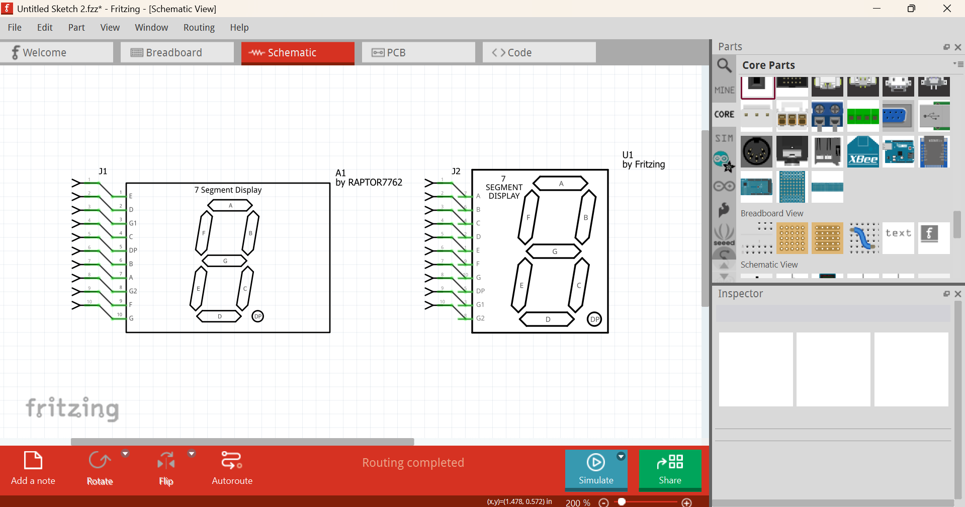
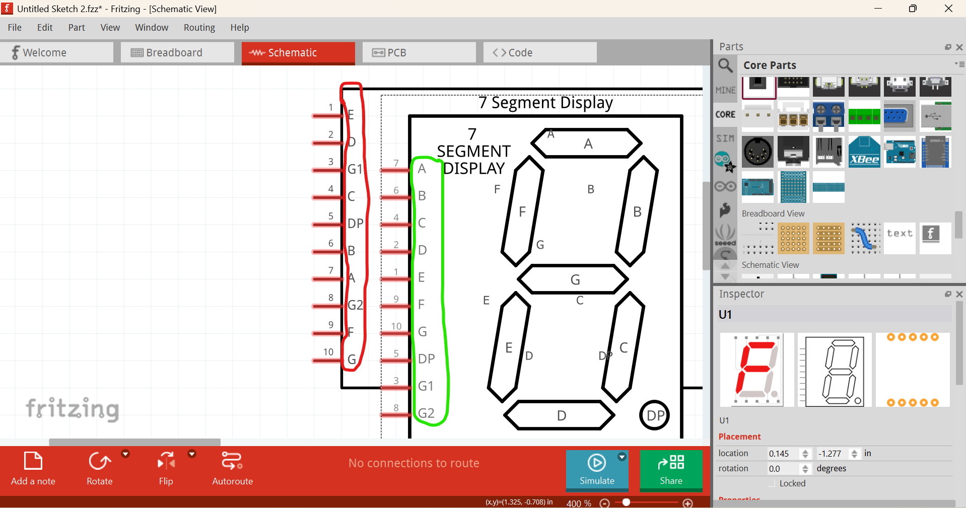
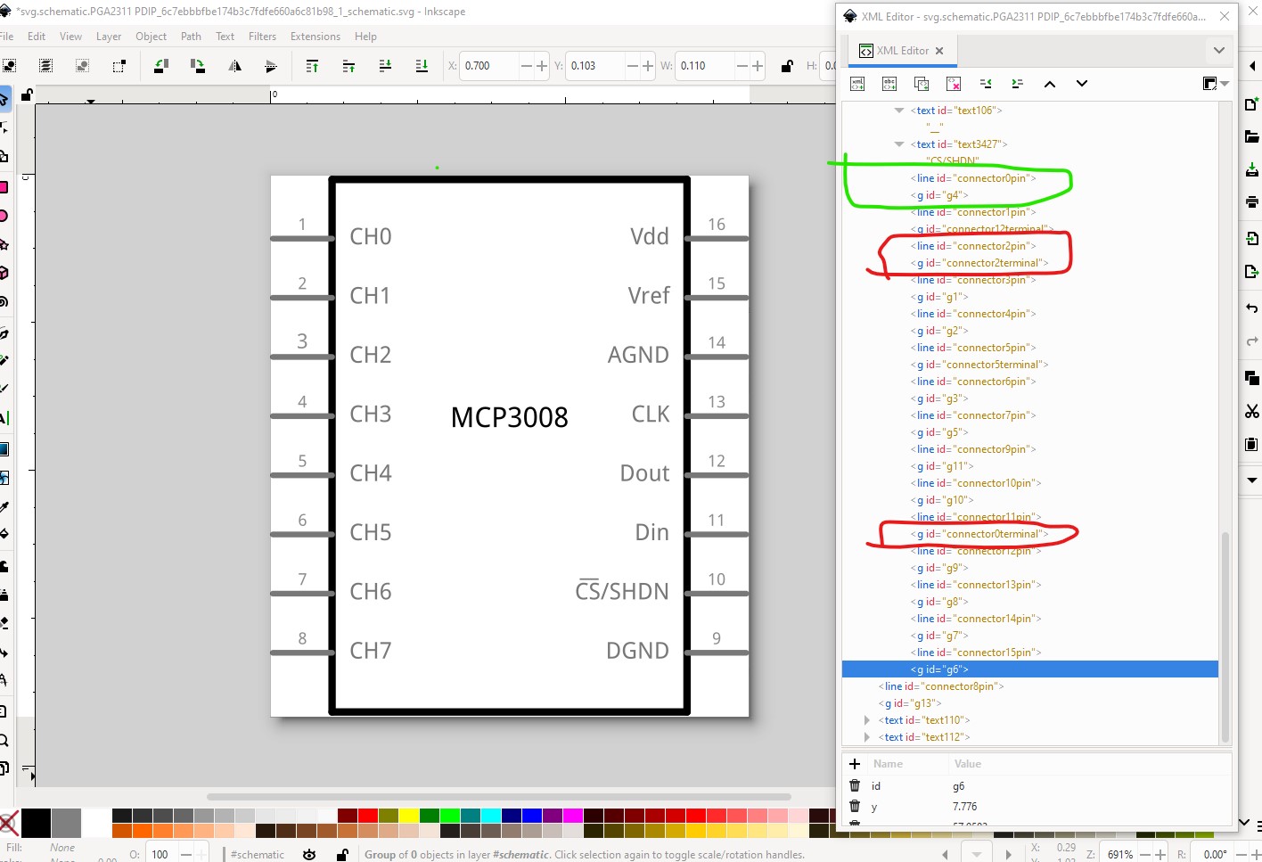
connector0terminal exists (as a group which is invalid, but it exists) so I don’t know why the alignment is correct to the end of the pin. Connector1terminal doesn’t exist but the connection is to the middle of the pin (and should be to the end I would expect.)

Peter

Ya so I fixed the schematic

The connectors in breadboard view are screwed up — not just undefined but also wrong order

I went through the Inkscape schematic extension and did some copy-pasting