Gravity ENS160 Air Quality Sensor.fzpz (46.6 KB)
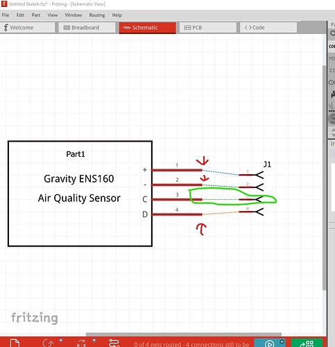
Not bad, but a couple of issues. Schematic should have pins on 0.1in boundaries to match other parts is the main one
The C pin is aligned correctly, the other three need to move in the direction of the red arrow to align with the grid lines.
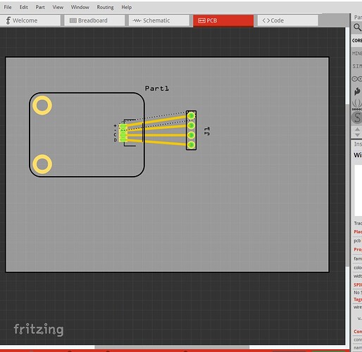
while pcb works fine, a better (and what I would do if making this part) is to suppress pcb view in the fzp file like this:
current fzp
    <breadboardView>
      <layers image="breadboard/Gravity ENS160 Air Quality Sensor_47f8fe94b215ebda99e1a210a725edef_8_breadboard.svg">
        <layer layerId="breadboard"/>
      </layers>
    </breadboardView>
    <schematicView>
      <layers image="schematic/Gravity ENS160 Air Quality Sensor_47f8fe94b215ebda99e1a210a725edef_8_schematic.svg">
        <layer layerId="schematic"/>
      </layers>
    </schematicView>
    <pcbView>
      <layers image="pcb/Gravity ENS160 Air Quality Sensor_47f8fe94b215ebda99e1a210a725edef_8_pcb.svg">
        <layer layerId="silkscreen"/>
        <layer layerId="copper1"/>
      </layers>
fzp with pcb view suppressed
    <breadboardView>
      <layers image="breadboard/Gravity ENS160 Air Quality Sensor_47f8fe94b215ebda99e1a210a725edef_8_breadboard.svg">
        <layer layerId="breadboard"/>
      </layers>
    </breadboardView>
    <schematicView>
      <layers image="schematic/Gravity ENS160 Air Quality Sensor_47f8fe94b215ebda99e1a210a725edef_8_schematic.svg">
        <layer layerId="schematic"/>
      </layers>
    </schematicView>
    <pcbView>
      <layers image="breadboard/Gravity ENS160 Air Quality Sensor_47f8fe94b215ebda99e1a210a725edef_8_breadboard.svg">
        <layer layerId="breadboard"/>
      </layers>
    </pcbView>
basically replace the pcb image file (which must exist, the part will break if it does not) with a copy of the breadboard file entry. That suppresses the part entirely in pcb view. In addition change label from part1 to A (for assembly) like this
<label>Part1</label>
to
<label>A</label>
(Fritzing will automatically add and increment the number on the end), otherwise a good job.
Peter
Thank you for your feedback, Peter! I truly value your suggestions and will definitely consider them for future updates. I appreciate your detailed insights and the time you took to help me enhance my design.
Check out my recent post, “Fritzing Check Part for Gravity ENS160 Air Quality Sensor.” In this post, I explain how the FritzingCheckPart tool can save time and prevent issues before finalizing your custom part. I’d love to hear your thoughts!
Read the full post here : Fritzing Check Part for Gravity ENS160 Air Quality Sensor
By and large looks fine (I wrote FritzingCheckPart.py) It will not deal with .fzz files as they are sketches not parts and in a different format. It could (but currently doesn’t) unzip and process .fzpz files but not enough people use it to make further development worthwhile. Most people find part making too complex. This tutorial covers making parts if you haven’t seen it (and includes FritzingCheckPart.py)
Peter
Gravity ENS160 Air Quality Sensor.fzpz (46.8 KB)
I have created a new version of this part after implementing the suggested changes:-
- I moved the pins to have 0.1-inch spacing in the schematic view.
- Renamed the part label to “U”.
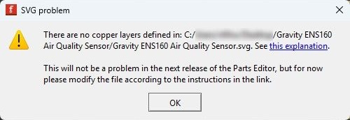
- Regarding suppressing the PCB view, I encountered an error message, as shown in the image below, when loading the breadboard image as the PCB. Therefore, I have kept the original PCB image.

U is for ICs, a board like this should be A (for assembly.)
to suppress pcb view (which is the sensible approach as this won’t fit on a pcb) change the .fzp file (parts editor won’t work here you need to edit the file, like this:
edit part.Gravity ENS160 Air Quality Sensor_ce62e77aa6a56f8fec43c1fb89d0cd90_2.fzp
and replace
  <pcbView>
   <layers image="pcb/Gravity ENS160 Air Quality Sensor_ce62e77aa6a56f8fec43c1fb89d0cd90_2_pcb.svg">
    <layer layerId="silkscreen"/>
    <layer layerId="copper1"/>
   </layers>
  </pcbView>
with
  <pcbView>
   <layers image="breadboard/Gravity ENS160 Air Quality Sensor_ce62e77aa6a56f8fec43c1fb89d0cd90_2_breadboard.svg">
   </layers>
  </pcbView>
which replaces pcb view with the breadboard svg (which Fritzing will not render leaving pcb blank, but it requires something to render to work.) It would be desirable to use Randy’s schematic extension in Inkscape for schematic as it will format it correctly but the current one will work.
Peter

