A few problems with this part. I assume this is the DFRobot sen-0515 part (the url in the part points to the sensor not the board web page)?
Breadboard
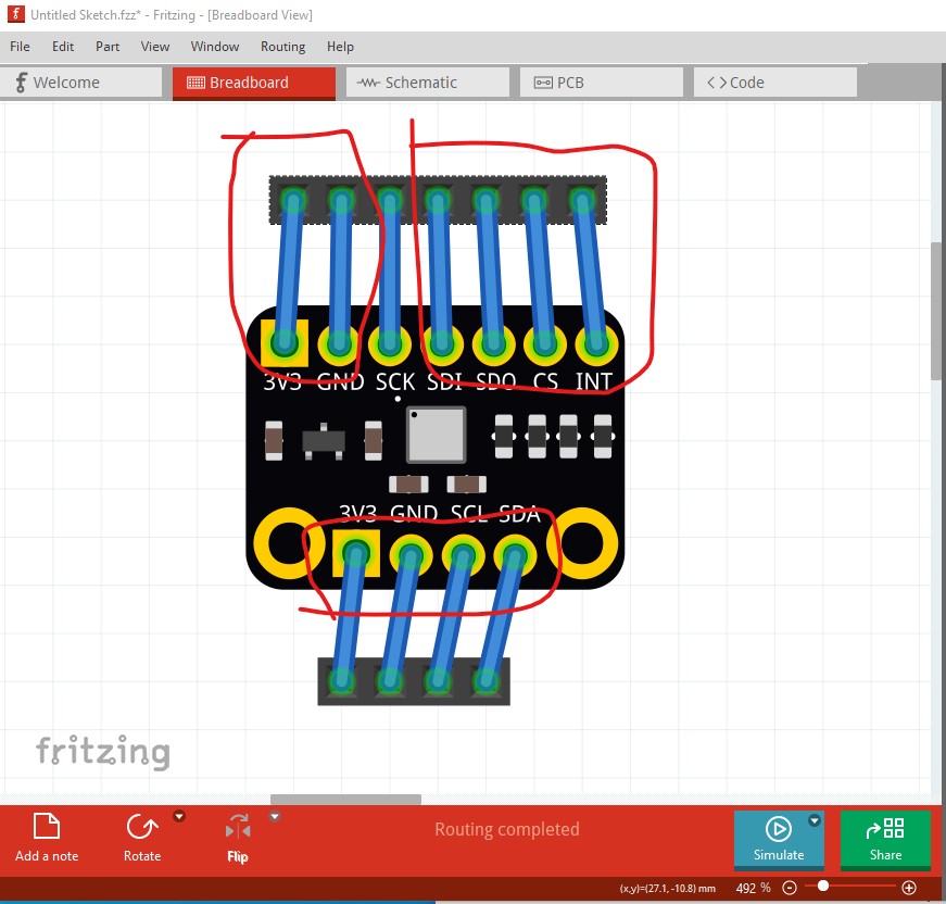
the scale looks to be slightly off. The connectors should be on 0.1in boundaries (standard 0.1in header) but as we see they are slightly wider than a standard header. The top third pin from the left is the only one that looks aligned.
schematic
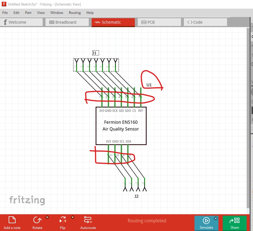
Is correctly aligned but the terminalIds (which are present) are not positioned correctly They should be on the top of the pin (or the bottom of the pin on the bottom) so the wire connects to the end of the pin instead of the middle. Your best bet here is to use Randy’s Inkscape Fritzing schematic extension which will automatically create correct schematics. In a recent post on the forum I fixed up a part for someone and used it there.
pcb
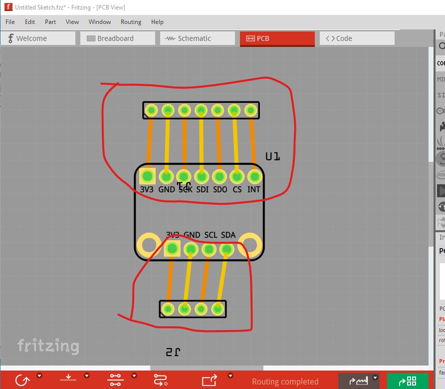
much the same problem. The pads are not aligned to 0.1in and thus won’t fit a standard header. In addition the hole size is way too large. The current holes are 0.051181in, for a standard 0.1in header they should be 0.038 in (i.e quite a bit smaller.) If you haven’t seen it this tutorial on part making may help you out.
(it gets posted a lot when people ask about making parts.) Hope this helps, if you have questions feel free to post them.
Peter