Fermion ENS160 Air Quality Sensor.fzpz (33.9 KB)
A few problems with this part. I assume this is the DFRobot sen-0515 part (the url in the part points to the sensor not the board web page)?
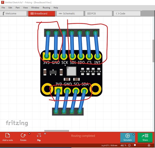
Breadboard
the scale looks to be slightly off. The connectors should be on 0.1in boundaries (standard 0.1in header) but as we see they are slightly wider than a standard header. The top third pin from the left is the only one that looks aligned.
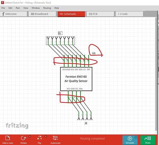
schematic
Is correctly aligned but the terminalIds (which are present) are not positioned correctly They should be on the top of the pin (or the bottom of the pin on the bottom) so the wire connects to the end of the pin instead of the middle. Your best bet here is to use Randy’s Inkscape Fritzing schematic extension which will automatically create correct schematics. In a recent post on the forum I fixed up a part for someone and used it there.
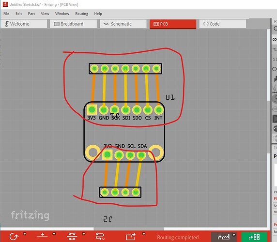
pcb
much the same problem. The pads are not aligned to 0.1in and thus won’t fit a standard header. In addition the hole size is way too large. The current holes are 0.051181in, for a standard 0.1in header they should be 0.038 in (i.e quite a bit smaller.) If you haven’t seen it this tutorial on part making may help you out.
(it gets posted a lot when people ask about making parts.) Hope this helps, if you have questions feel free to post them.
Peter
Thank you for the detailed feedback and tutorial link. I will make the necessary adjustments and update this part.
Yes, both DFRobot’s Gravity and Fermion ENS160 Air Quality Sensors are based on ScioSense’s new ENS160 sensor chip. I have written a post on Quora to explore what sets these two apart. I’d love to hear your thoughts!
Read the full post here: Gravity ENS160 vs. Fermion ENS160: What sets these air quality sensors apart?
The gravity part uses 2mm grove connectors to fit the Gravity eco system and thus be plug and play (but won’t mount on a pcb easily) appears to be the main difference. They are aimed at different markets.
Peter
Fermion ENS160 Air Quality Sensor.fzpz (34.1 KB)
I have created an updated version of this part after implementing the suggested changes:
- Aligned the connectors in the breadboard view to match the standard 0.1" header.
- Positioned the terminal IDs in the schematic view to ensure the wire connects to the end of the pin.
- Adjusted the connector hole size in the PCB view to 0.038" for a standard 0.1in header.
Peter, your suggestion to use Randy’s Inkscape Fritzing schematic extension to automatically generate accurate schematics was extremely helpful. Thank you for that! It made the process of creating the schematic very easy. However, I discovered that it is a hassle to make Fritzing accept text from Inkscape, so I had to work around it to format the text correctly.
Most likely you are running in to px in the font-size definitions. FritzingCheckPart.py automatically removes them (along with other things) but using a text editor to remove all instances of “px” usually works as well.
Peter


