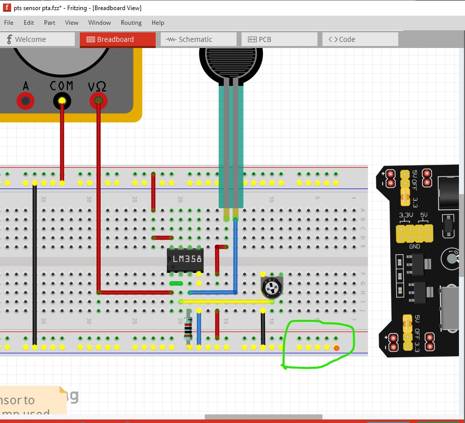
I did a search for a breadboard power module : Beginner looking for breadboard power but when I download that Fritzing part all is shows is a breadboard and not the actual board. Mine is an Elegoo power supply module with 5v and 3.3v options on either side. Help to find the part would be most welcome.
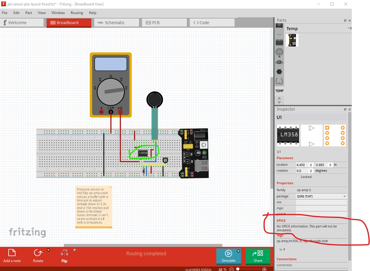
I have done the best I can but not sure how to get a simulation working, Help would be appreciated as I think I am almost there. pts sensor pta.fzz (99.4 KB)
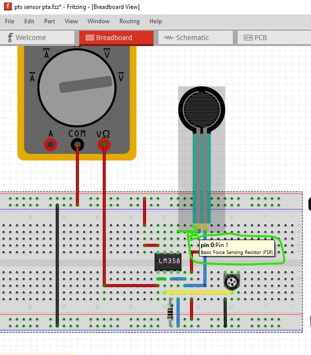
You have a variety of problems, some fixable, some not immediately. First your layout is wrong (which is fixable):
Here I clicked on the green arrow in the lower right of the image. That lights all connections in the net yellow which indicates a short between power and ground (and that the groups in the power supply part are not correct but that won’t matter here.)
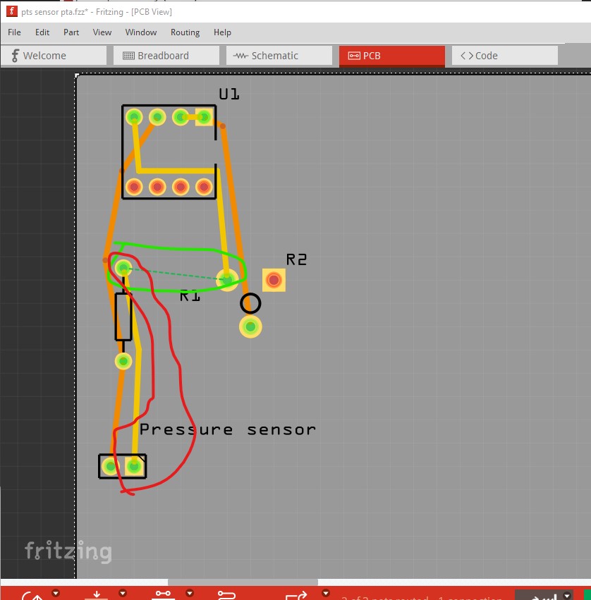
then in pcb I did the same to find pin0, as we see from the rats nest line that connects R1 to ground, that should not connect to the FSR but rather like this
However this still won’t simulate because a number of the parts don’t have spice information and without it simulation won’t work. The fsr does not have spice information (it is basically a pot so it could be added and may have been in the simulation parts.)
there may or may not be a part for the lm358 with a spice model in it. I think there may be a bin with simulation parts in it @fai (who wrote the simulator) can probably give you better advise on what is available than I can.
@vanepp is right. You must use parts with spice models.
FSR: You must replace it by a resistor or potentiometer to be able to simulate it. Also notice that you are using an obsolete FSR. There is a better part with a better symbol in the sch. To use it, simply replace it with the one in the CORE bin.
The power supply needs to be change to a battery to be able to simulate it.
LM358: You must find a spice model from one of the manufacturers (e.g., https://www.st.com/en/amplifiers-and-comparators/lm358.html#cad-resources ) and add it to the part. This can be a bit tricky and it is not super straightforward.
So, Fritzing has the functionality to do it, but we are still working to integrate more models and make it easy to simulate more parts. Currently, we are trying to integrate some AD parts with spice models that will work off the shelf, but it may not be easy for non developers.