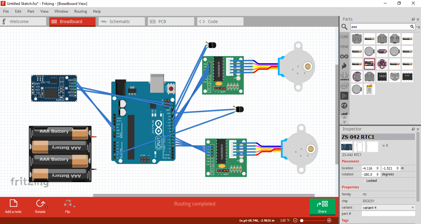
this is for flip Clock project the motor 1 move 6 degrees.
motor 2 move 15 degrees every hour.
the well that hold the flaps have magnet that work like home position if the program didn’t pass the magnet when it suppose to the DLC will tell him to search the home position and get the time right.
to the batteries I didn’t know how to connect it
by the way i don’t know how to program well
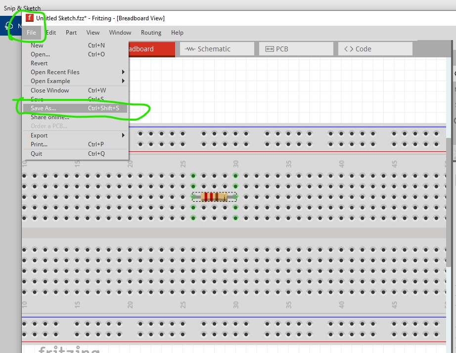
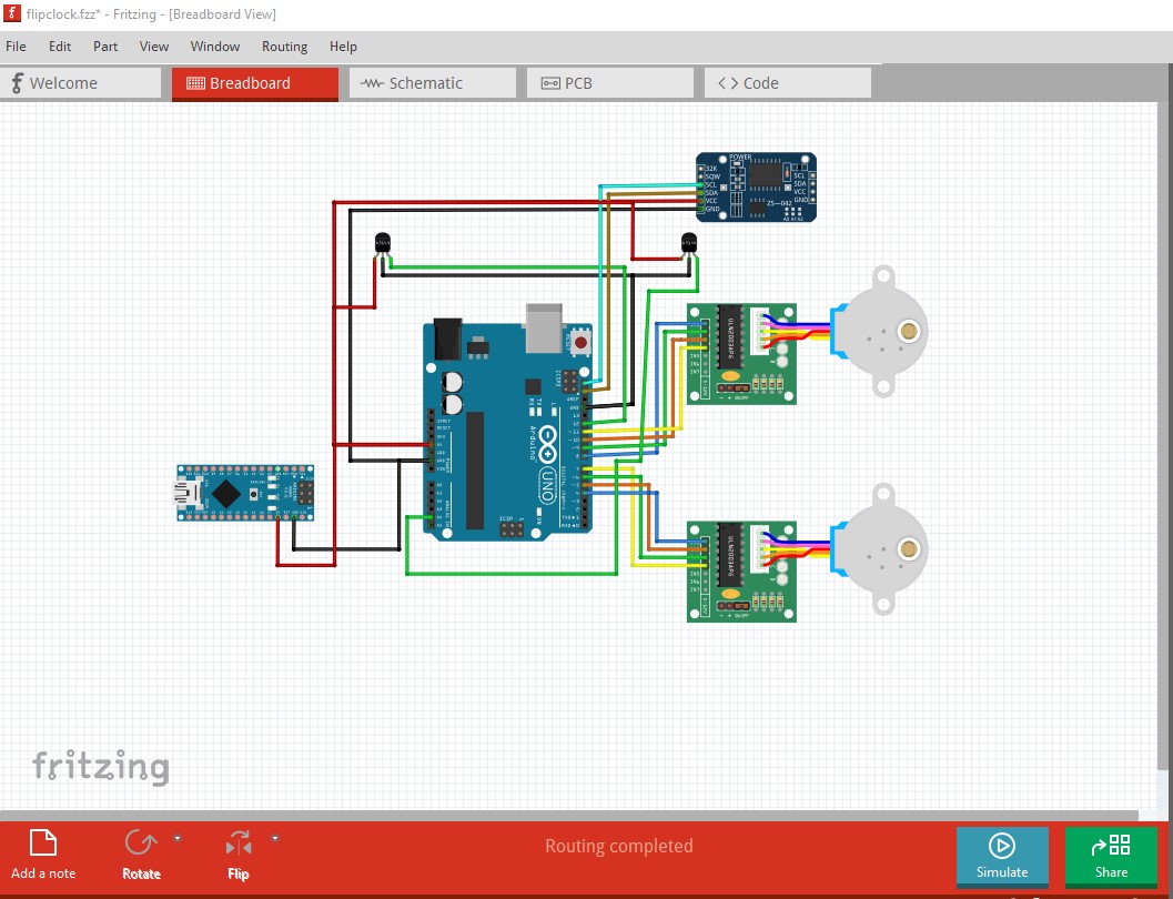
Rather than pictures which aren’t very useful in debugging it is a better bet to upload the sketch (the .fzz file after you save the sketch, upload is 7th icon from the left in the reply menu and will accept .fzz files.) Presumably the battery should connect to ground and VIN although at only 6V it may not have enough voltage for VIN (I think the minimum may be 7 volts.) If you want help with the code you probably need to upload that as well (you can cut and paste the C code in to a post.)
As noted, pictures are basically worthless. Without the .fzz file of the sketch it is basically impossible to make any useful comment. It is not possible from the image to see how the drivers are connected. If you want an external line powered power source use one of the generic power supplies available here
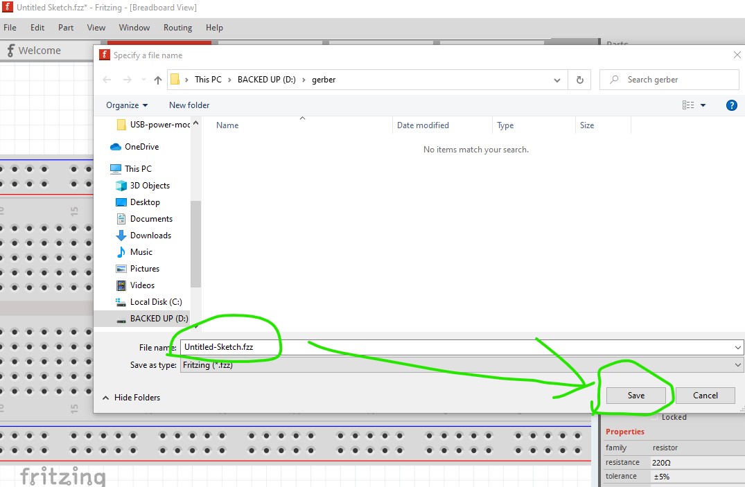
then press save which saves the sketch as a .fzz file. Fritzing will now restore the file if you double click in the .fzz file. I assume you must already know this as otherwise you would need to recreate the sketch every time, perhaps my terminology is unclear.
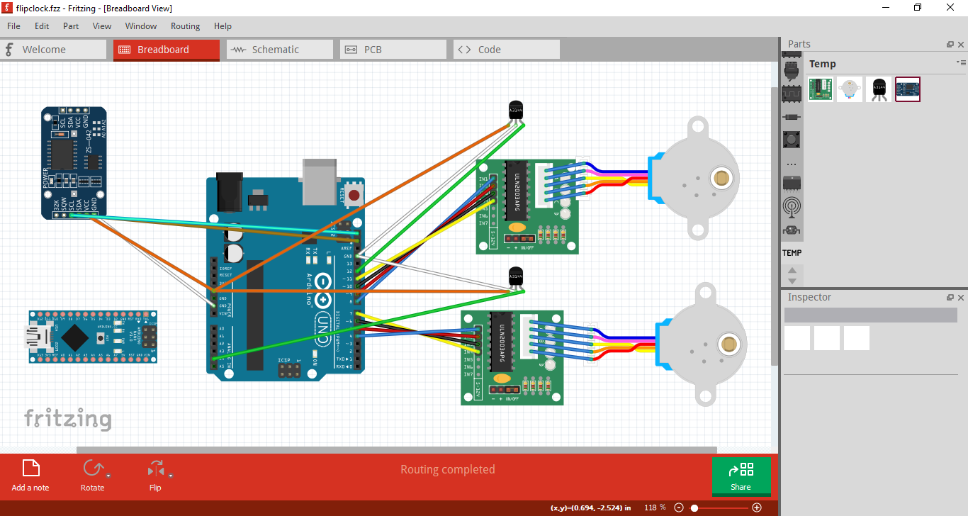
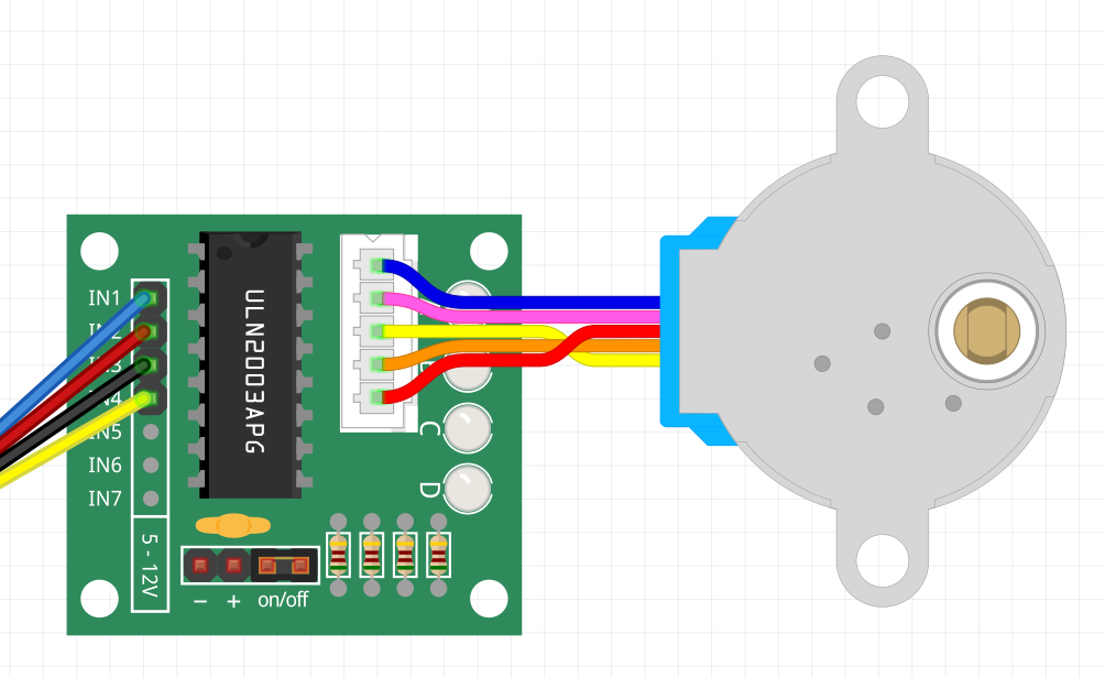
Only a suggestion from my side: you can connect the stepper motors directly to the stepper drivers like in the following image (saving a lot of redundant wires)
It requires the correct configuration in the parts and that (in this case) that you move the board in to alignment with the connector on the motor (the other way will not connect.) With that on to your sketch. First I rerouted breadboard to make it easier to read
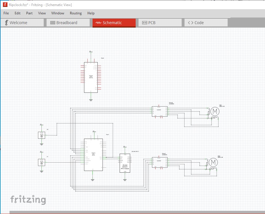
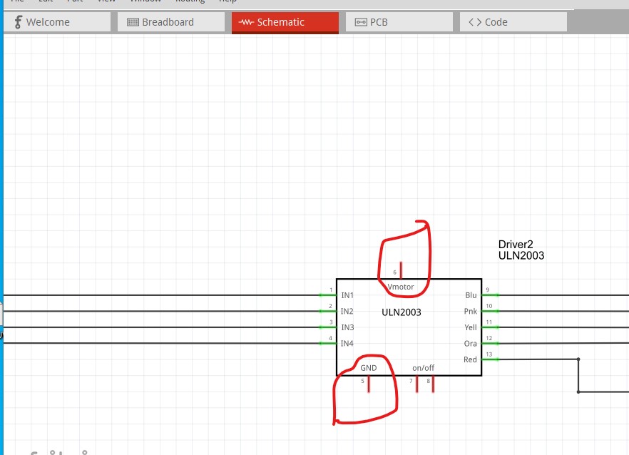
so you need to connect a ground and a motor power source to those pins (in both breadboard and schematic.) Then there is a problem with the U1 A3144. It is connected to A4 (which is also SDA as the (a5/SDA on the Uno indicates) and thus won’t work. The A3144 needs to move to another digital pin. It also needs a 10k pull up resistor to 5V as detailed in this post
I don’t know if the .1uf cap is actually needed or not but the pull up resistor is. That should fix all the obvious errors (but will also require changes to the code in the Arduino.) The changes are this sketch