Hi all,
do you know if exists some parts like the E70 module?
Pin No
Pin item
Pin direction
Pin application
1、2、3
GND
Ground
Ground electrode
4、5、6、7
NC
Reserved pin
Reserved, to be floated
8
VCC
-
Positive power reference of the module, voltage range:2.2V ~ 3.8V DC
9、10
GND
Ground
Ground electrode
11
PA_EN
Output
External PA control output, valid in high level (floatable)
12
LNA_EN
Output
External LNA control output, valid in high level (floatable)
13
M2
Input
M2, M1, M0 jointly decide the 8 working modes; an external 1k protective resistor shall be connected in series when in use.
14
RESET
Input
Module reset pin,valid in low level
15
GND
Ground
Ground electrode
16
AUX
Output
It is used to indicate the module operation status, for user to wake up the external MCU, the module outputs low level during self-checking and initialization at power on, it can be configured as open-drain output or pull-up output,please refer to parameter setting part (can be floated)
17
TXD
Output
It also can be usedas TTL serial port output connecting to external RXD input pin. It can be configured as open-drain or push-pull input,please refer to parameter setting part
18
TCKC
Input
JTAG TCKC
19
TMSC
Input
JTAG TMSC
20
RXD
Input
TTL serial port input connecting to external TXD pin. It can be configured as open-drain or high pull input, please refer to parameter setting part.
21
M1
Input
M2,M1, M0 jointly decide the 8 working modes;(Cannot be floated,it can be grounded when not used)
22
M0
Input
M2,M1, M0 jointly decide the 8 working modes;(Cannot be floated,it can be grounded when not used)
This part should do what you want. Note before ordering boards print the pcb footprint out at 1:1 scale and compare it to a real part to make sure it fits. This was created from the data sheet (I don’t have one to test) and thus may not be correct. Also the pin numbers match the data sheet pin numbers (and the internal pin numbers are therefore different.)
It is possible, but I don’t see a point to doing it. The current part is the typical output for an smd part (an adapter board that converts it to fit in a breadboard.) I don’t see anything useful to do with an SMD part in breadboard. If you explain what you want to, do perhaps I will reconsider.
Hi vanepp,
It’s true, I must explain the request.
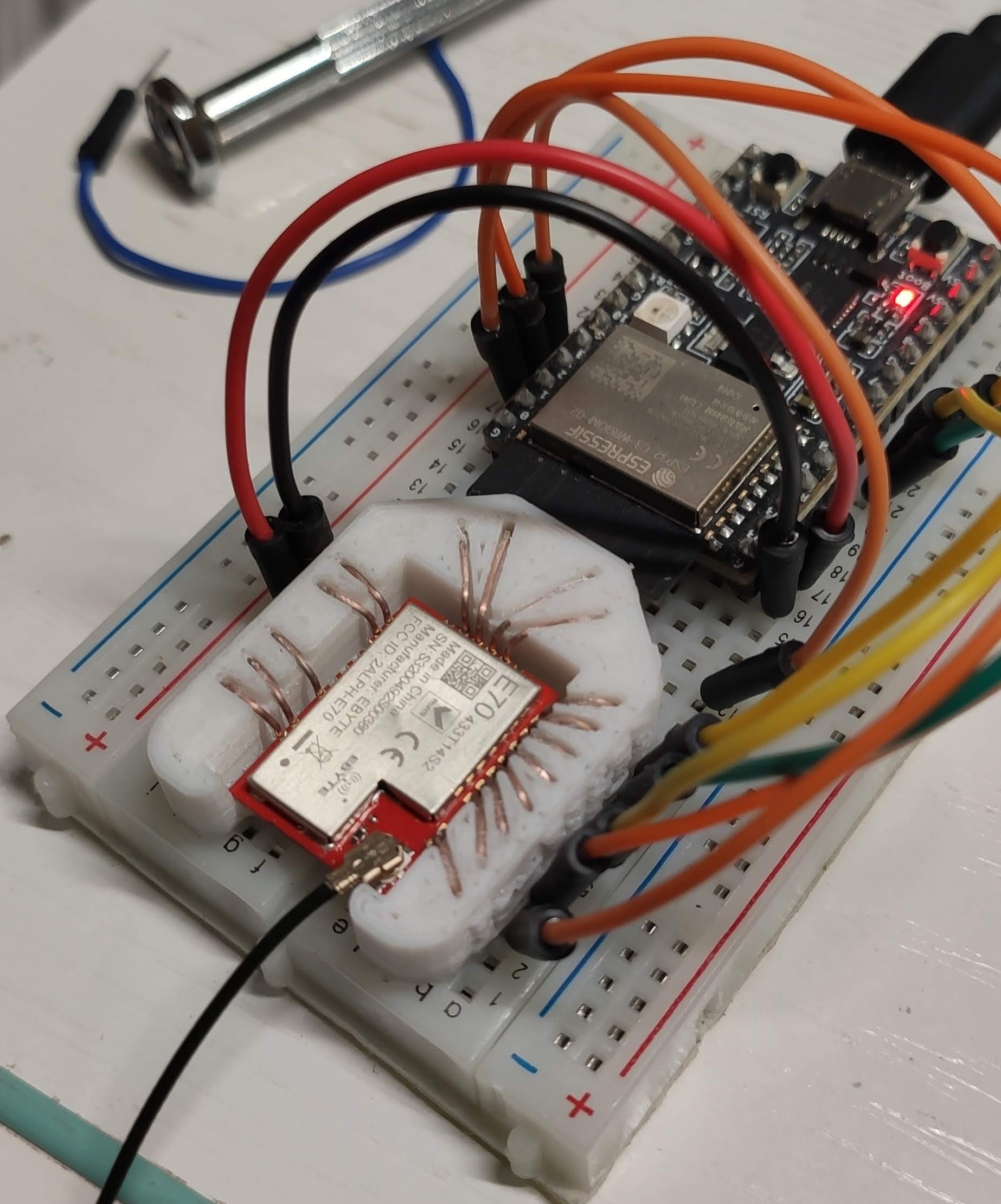
I created a 3D-printed socket to adapt all the series of e70 s2 (with various frequencies) to the breadboard, and the connection pins are visible. By following the wire, It’s like connecting directly to the SMD.
I would need the mapping of pins to breadboard connectors to do anything useful with this. For instance it appears from the picture that only 4 of the 6 end pins have connections I would need to know what those pins are and to which breadboard row they are supposed to go. A list of the pins with which breadboard row they should go to would do it (and even then I’m not sure this is worth doing as it isn’t general purpose unlike the module which can be bought!) You could also edit the breadboard svg your self to do what you want. Instructions for doing so are available in this tutorial (although it is not easy.)
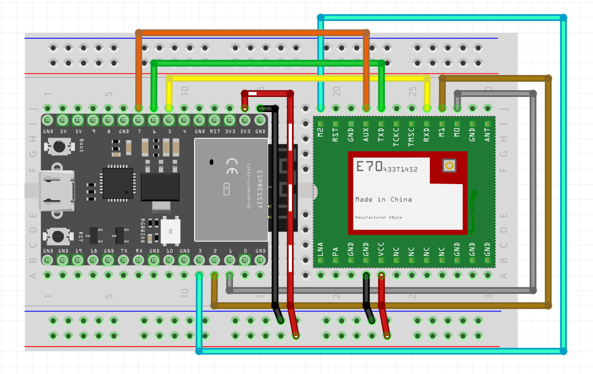
the easiest way to do it would be to modify the current carrier to match the layout of the adapter to add blank pins where needed if needed. It looks like the current carrier should be pretty close (and prehaps identical!) if you ignore the unused pins, as the 6 end pins are split between the top and bottom adapter rows which looks to be what you have and assuming the first and last pins of the 6 on the end are unused as it appears the current adapter should do what you want without change.
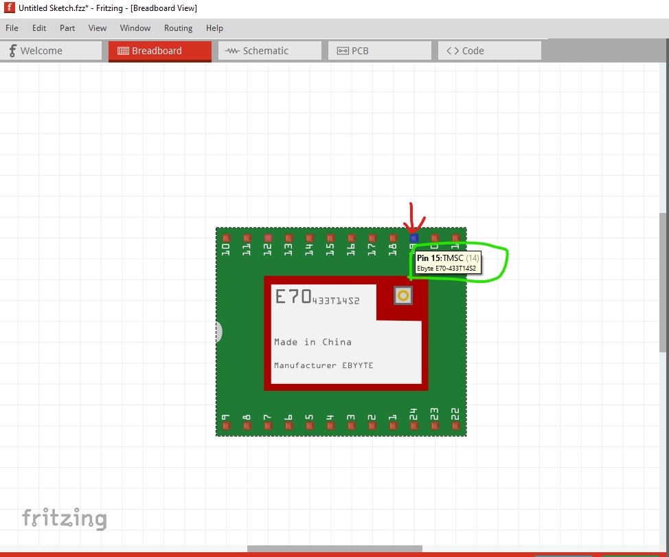
In case you aren’t aware of this, hovering over a pin (in any view) will bring up the pin description (as long as it is defined in the part which it is in this case)
here I moved the mouse over pin 15 (red arrow) which brings up the pin description (green circle) that may help in identifying the pins (which as noted, it looks like may be correct to do what you want now with no changes to the part!)