Cygwin64 /usr/bin/env: ‘python3’: No such file or directory

I am having difficulty in attempting running the script in Cygwin64. However I’m not sure if Cygwin64 is installed properly and on the right drive (installed on D: at present) as I have 2 drives available (C: & D:).

The error prompt after is:
$ fritzingcheckpart.py \test\svg.pcb.CD4060BE_dip16_300mil_pcb.svg
/usr/bin/env: ‘python3’: No such file or directory

Please help, I’m not a Linux user (but I was quite good with DOS commands) so learning the system terminal commands shouldn’t be a problem.

I’ve also installed IDLE Python 3.8.

Being able to check parts would be beneficial.

I think Fritzing EDA is a remarkable piece of software and quite intuitive. Everyone who is involved in the development of this software are doing a great job!

Kind regards

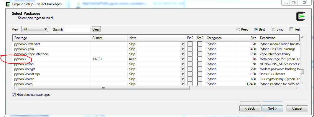
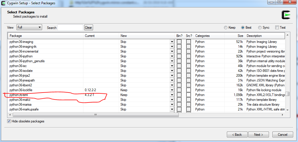
Welcome aboard! Python 3 isn’t loaded by default in cygwin, nor is lxml so you need to run cygwin setup and select both (they will likely pull in a bunch of dependencies as well):

python3:

lxml

As well FritzingCheckPart.py assumes you are familiar with the structure of the svg files so this set of tutorials may be helpful as well:

Peter

Hi Peter

It’s good to be aboard (in whatever capacity I can help with). Sadly I’m not a programmer (the last computer language I learned was Turbo Pascal).

Excellent, I’ve re-installed Cygwin with the selections shown… It works (holy cow!). The Linux command lines were easy to figure out (similar to DOS), and “FritzingCheckPart” ripped through the part files like a whirlwind making its corrections. AWESOME!

Inkscape was a steep learning experience, but I think I have it figured out. Although I thought the setting up of the 1/10th’s of an inch was a bit odd when 1/8th’s of an inch are displayed on the rulers yet the grid clearly shows 1/10th’s of an inch with subdivisions of course (a bit confusing).

However is was self explanatory from your document standards setup instructions with regards to the scale, colours, & other system/document standards required for part creation. Especially the scale (1000/96)=10.416666667.

So as I have clearly given away, I have created a component… The CD4060BE, a 14 stage binary counter. The pads on the PCB svg are elongated/oblong which proved to be a challenge, but I think I’ve cracked it.

Could I ask you to check this part please, if it’s not too much of an inconvenience. Also, is there any other scripts I should run to complete the checking of all the component files, like the other scripts provided (pp.py, pptools.py, fritzingtools.py).

I did get an error stating the part is through hole and if I wanted an smd part I should remove the copper0 definition. Other than that, FLAWLESS!

I think I may have the “part creating bug”. I’m sure there is plenty for me to learn about the “pleasures and pitfuls” of part creation. Hopefully I have attached the component zip file correctly (used 7-zip).

TI_CD4060BE_DIP16_300MIL.fzpz (8.6 KB)

Kind regards

Glenn

Yes, Inkscape still bites me occasionally (I think because I mistype with a label not selected and hit a hot key that does something I don’t know how to correct), and has a number of issues (such as style and px in font names that conflict with Fritzing but over all it works well enough. The original plan was to make parts editor do the entire job for itself, but I’m not sure we will ever get there. Some things in breadboard will likely always need a svg editor I think.

You look to have nailed it perfectly! There doesn’t appear to be a way to do this with only a path. A circular path will work (although it is less useful because the hole size is harder to change than a circle), but the gerber output code apparently won’t process a path with a circular hole correctly, it looks to need the radius of the circle to work.

A couple of minor nits, the label field in the .fzp file should likely be U so the chip shows up as U1, U2 etc to match the others. The schematic svg has some strokes and fills set as #8c8c8c8 rather than #55555 (but many existing parts in core are this way to, I think parts factory may generate this for the generic IC as well and I haven’t gotten around to fixing that yet.) It would be preferable for schematic to be smaller as space in schematic is valuable, but again many parts in core and the Parts factory both generate this type of schematic.

The message isn’t an error, just information (I will likely remove it in the new version of the script or just reduce it to something like “this is a through hole part”) , so FLAWLESS is indeed correct. While we need developers the sad fact is that the code is so complex that the likely path forward is donations funding professional developers to finish the coding, so people making parts are valuable as well. There aren’t that many folks making parts any more. Good job!

Peter

Peter

Thanks for the valuable input and information. Its true there are conflicting drawing and colour standards within the core parts library which led me down the path of continuing with the existing colour of #8c8c8c, which of course was originally within all of the associated part files for the “generic IC” template. Of course, I have corrected the colour and the label as suggested.

TI_CD4060BE_DIP16_300MIL.fzpz (8.6 KB)

In future I shall use the Fritzing standards outlined on the “Graphic Standards” page Fritzing’s Graphic Standards and make good use of the “Graphics Template Files” Fritzing’s Graphic Templates.

One final request, would the other scripts be of use to me in the future (pp.py, pptools.py, fritzingtools.py). Also do you have any recommendations for other svg editors.

So a friendly note to all of you having this issue its a simple fix, when you install Cygwin make sure you install the python3 “packages and lxml dependencies” otherwise FritzingCheckPart.py will not work.

Kind regards

Glenn

We need to update the graphics standards, part file format document and certainly the templates (which are currently just plain wrong, so don’t depend on them!) but we haven’t gotten there yet. Fritzing development died in about 2016, and has only in the last year or so restarted resulting in the 0.9.4 release in late 2019. There is a lot of mostly invisible work going on in the web site, the forum and mostly in the distribution tool chain (which was non existent and had to be recreated to make the 0.9.4 release) Most of the folks who are familiar with the code and the app have moved on, so there is a knowledge vacuum and not a lot of people working on it yet. We hope that donations are going to allow hiring professional developers to finish the code, as it is considered to complex to be done by volunteers.

pp.py will pretty print an svg file (FritzingCheckPart.py does this using pptools.py.) pptools.py and fritzingtools.py are the libraries for FritzingCheckPart.py. What may be of use is FritzingCreateFzpConnectors.py which is available on github in the FritzingCheckPart repo but not part of FritizngCheckPart. What it does is create the fzp connector definition boiler plate like this:

FritzingCreateFzpConnectors.py t 2

which writes a file called t which contains:

$ cat t
  <connector id="connector0" type="male" name="">
    <description></description>
    <views>
      <breadboardView>
        <p svgId="connector0pin" layer="breadboard"/>
      </breadboardView>
      <schematicView>
        <p svgId="connector0pin" layer="schematic" terminalId="connector0terminal"/>
      </schematicView>
      <pcbView>
        <p svgId="connector0pin" layer="copper0"/>
        <p svgId="connector0pin" layer="copper1"/>
      </pcbView>
    </views>
  </connector>
  <connector id="connector1" type="male" name="">
    <description></description>
    <views>
      <breadboardView>
        <p svgId="connector1pin" layer="breadboard"/>
      </breadboardView>
      <schematicView>
        <p svgId="connector1pin" layer="schematic" terminalId="connector1terminal"/>
      </schematicView>
      <pcbView>
        <p svgId="connector1pin" layer="copper0"/>
        <p svgId="connector1pin" layer="copper1"/>
      </pcbView>
    </views>
  </connector>

This allows you to delete the connector section of an fzp file and replace it with the contents of t, which will have the pins correctly configured for various configurations (there are flags available in FritzingCreateFzpConnectors.py for different output formats.) That lets me just add the name and description fields from an existing or new part without having to type all the boiler plate code that is always the same. I have some more scripts (that are too rough to post yet) that will bulk add the connector names to an svg file if it is formatted correctly (the connectors all at the bottom of the svg) and allow you to renumber the connectors to add or move them around. I need to figure out what all the useful commands are (I currently modify the source code of the script to do what I need) and figure out how to make that happen from command line arguments. This reduces the time it takes to make a new part by a large margin. At the moment it is a background task, as the main task is a new version of FritzingCheckPart which will do more and eventually be part of the part submit tool chain to check submitted parts, but that is going slowly (I’m not all that good at development :slight_smile: .) As to svg editors, I stick with Inkscape because it is open source and thus the common one used, Illustrator is probably the second most common (but is not free), though I don’t know of an Illustrator in Fritzing expert that posts here, Gravid from Corel (search for forum posts by @opera_night , he both has useful information on things like cnc milling boards, odd shapes in boards and slots and Gravid (I may have the name wrong there :slight_smile: ). It isn’t open source but has a free version I think and looked pretty good. There is a new version (1.0) of Inkscape coming (maybe here by now I haven’t checked recently) but last I tried it 6 months or more ago it had bugs that made it not usable for Fritzing. It does fix some of the annoying Inkscape bugs (not being able to cut and paste between Inkscape windows for instance.)

Peter

My main background is software development. If we can setup a chat channel someplace, I may be able to help out. We could use the slack channel for WCRS. I can send invites, and add people there. Maybe I can even convince you to help startup a branch in Vancouver :slight_smile: “Western Canadian Robotics Society”

Check with @KjellM to see if there is room on the Fritzing slack channel. I’m already there (although there hasn’t been activity for months :slight_smile: as are a number of the other developers. I don’t know if it is the free version and thus limited to 20 people or a paid version, but that is probably the best place to do this as a source of documentation.

I expect we probably have something, I know there is a Lego robotics group in town (I bought some extra Lego parts for some Yahboom Lego clone robots I have, and the person selling the parts was telling me I should come to the Lego robotics group …)

Peter

I dropped a message in his inbox.