Hi Peter
It’s good to be aboard (in whatever capacity I can help with). Sadly I’m not a programmer (the last computer language I learned was Turbo Pascal).
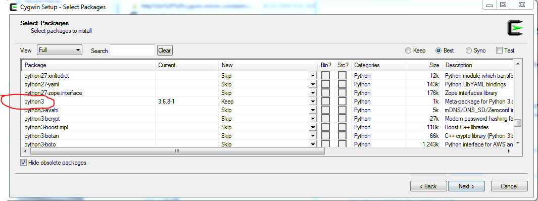
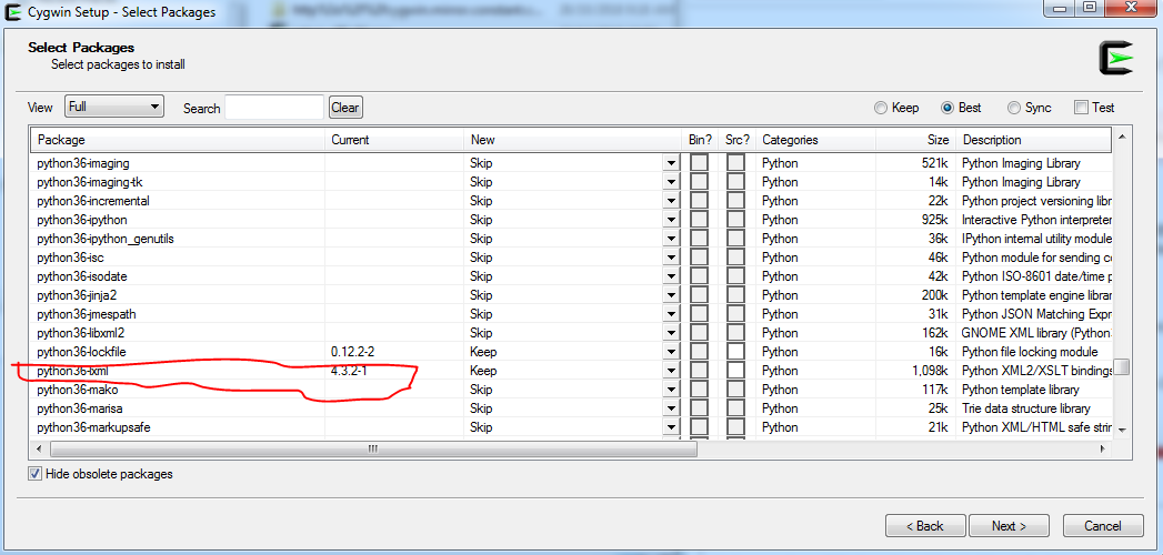
Excellent, I’ve re-installed Cygwin with the selections shown… It works (holy cow!). The Linux command lines were easy to figure out (similar to DOS), and “FritzingCheckPart” ripped through the part files like a whirlwind making its corrections. AWESOME!
Inkscape was a steep learning experience, but I think I have it figured out. Although I thought the setting up of the 1/10th’s of an inch was a bit odd when 1/8th’s of an inch are displayed on the rulers yet the grid clearly shows 1/10th’s of an inch with subdivisions of course (a bit confusing).
However is was self explanatory from your document standards setup instructions with regards to the scale, colours, & other system/document standards required for part creation. Especially the scale (1000/96)=10.416666667.
So as I have clearly given away, I have created a component… The CD4060BE, a 14 stage binary counter. The pads on the PCB svg are elongated/oblong which proved to be a challenge, but I think I’ve cracked it.
Could I ask you to check this part please, if it’s not too much of an inconvenience. Also, is there any other scripts I should run to complete the checking of all the component files, like the other scripts provided (pp.py, pptools.py, fritzingtools.py).
I did get an error stating the part is through hole and if I wanted an smd part I should remove the copper0 definition. Other than that, FLAWLESS!
I think I may have the “part creating bug”. I’m sure there is plenty for me to learn about the “pleasures and pitfuls” of part creation. Hopefully I have attached the component zip file correctly (used 7-zip).
TI_CD4060BE_DIP16_300MIL.fzpz (8.6 KB)
Kind regards
Glenn