Is it possible to create a part where I could move elements of the part around within the schematic view?
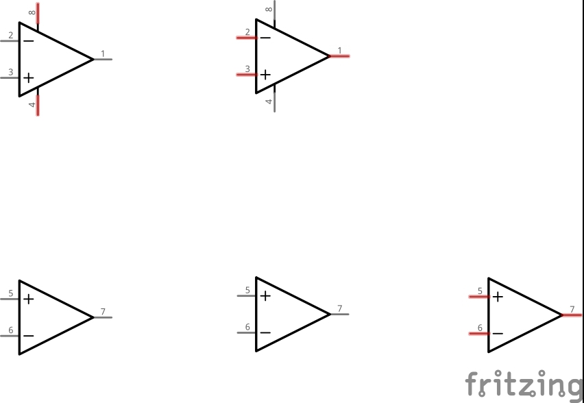
For example; When using TL074 quad Operational Amplifiers I have to make a huge work around. I first put in TL071’s (which can be individually flipped or rotated as required). I then make the circuit (usually copying schematics from books etc). Once this is done I then export an .SVG of the entire schematic and use this as a guide to make a bespoke TL074 (in an external graphics editor). Import this new bespoke TL074 schematic image into Fritzing and make the pin assignments. It would be awesome if Custom Parts could be made of multiple schematic elements.
Thanks for this wonderful software!
Yes, although it sucks you in to parts creation hell  . It is described in the fpz file format document at
Someone recently posted some CMOS gates using this technique which is where I found out about it from. Once I get a bit further along in parts creation hell I intend to use it.
Peter Van Epp
2 Likes
Thanks for this Peter!
This is exactly what I needed to know! 
At a glance, this seems fairly straight forward - just alter some attributes in the .FZP file and the part becomes a number of sub-parts.
I will update if I can simplify this explanation.
For now, here’s a link to the relevant section of the document you provided;
NoodleDriver
I’m still trying to wrap my head around parts creation starting from zero knowledge of xml or svg and so may have a negative bias sounds like you have experience already which may make it easier.
Peter Van Epp
1 Like
Well, I followed the instructions and this is what I came up with… At least I think I did it right…
LM358-Subparts.fzpz (12.7 KB)
1 Like
Almost, but it shouldn’t be leaving the extra images around nor creating 2 copies of the active image
(i.e. 2 copies of the op amp with pins 1, 2 and 3 when there is only one part on the schematic
This part from sgparry0407 works correctly (way to good to be mine  ):
):
4070 4 x 2 Input XOR Gate, multi-part - v3.fzpz (11.6 KB)
Peter Van Epp
1 Like
That’s not right… these are Fritzing’s instructions; 2.1 Part file format · fritzing/fritzing-app Wiki · GitHub
<g id="subpart1">
    <g id="subpart2">
        <g id="subpart3">
        </g>
    </g>
</g>
and the elements in that SVG must be redistributed to be children of those elements.
I don’t think the elements should be embedded… unless this is for something else…
I checked the 4070 and they are not embedded… makes a lot more sense that way.
“See one, do one, teach one”… you can’t do one if you can’t see one…
1 Like
Hmmm, looking back at Problem with 4xxx logic gates - can you reproduce this?
I don’t actually see the reference to the parts format file, so maybe I just saw that there and assumed that was the instructions.
Peter Van Epp
1 Like
That can’t be right either… Subpart1 includes pin3 and pin7 which is part of the first op-amp and subpart2 is the rest of the first op-amp. Subpart3 is the second op-amp… How do you split that up?
Maybe all the graphics should be included in subpart3… and just separate the connector pins. Also, the connector##terminals don’t work in this subpart schematic. 
EDIT: The connector##terminal problem was those 0,0 squares we were just talking about… An easy fix is to add width and height using an xml editor.
1 Like
My advise would be to send a message to sgparry0407, he has obviously figured this out (although I just now noticed there that the output pins in the 4070 are offset from the grid by a fraction in schematic when they are in the original place but snap in correctly when moved out) and the pins seem to connect correctly and he seemed happy to share. I think the forum should be copying him as I mention his id, but since it isn’t highlighted I think I’m not doing something it wants to identify another user.
Peter Van Epp
1 Like
If you load the part in from another view, the schematic may not be line up until you move it and it snaps into place. It is not a question of how to do it. It’s is really simple once you understand it… Actually, I think both ways are right depending on what you want to do with it… It’s just FZ fell short on instructions… They should have included an example of using the LM358 op-amp sub-parts…
Did you read that about the 0,0 squares and the easy fix? … I just forgot to check… It is weird that I can’t make them bigger in the graphics editor…
1 Like
No, is that in the parts format doc? I don’t see it there, and I like easy fixes!
Peter Van Epp
1 Like
Backup about 4 post…
I couldn’t change the size in CorelDraw so I changed with notepad++, that fixed the connector##terminals.
1 Like
Ah! Score one for Inkscape then, as its xml editor will let me edit them. Then take points off because I’ve just discovered while breaking bendable legs that Inkscape changes the order it writes xml out apparantly at random (i.e. the fields are there and the same, just in a different order so if you diff the two files you get a mass of changes most not relevant) or even realy there.) I’m back to the perl xml parser to see if I can make something fairly easy to actually do a useful diff of two Inkscape files so I can see what is changing. The joys of parts creation
Peter Van Epp
1 Like
That ‘4070 4 x 2 Input XOR Gate, multi-part - v3.fzpz7’ part by sgparry0407 has got the problem solved. I hope to get my head around this soon. 
For now I have made a little progress-
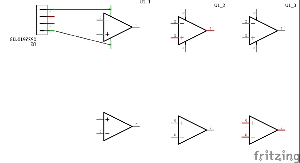
TL074 Quad Opamp (Movable3).fzpz (8.9 KB)
It looks good for the opamps but the power pins keep disappearing in schematic view.
The other problem is that the pins wont work either!  Getting there slowly!
Thanks for the help so far folks.
I’m glad to see it isn’t just me that is finding parts creation a hard slog although I’m no where near as far as being able to tackle movable parts yet. Currently bendable legs are eating my lunch. Just about to appeal for yet more help …
Peter Van Epp
1 Like
I think statute of limitations is up for an appeal…
1 Like
Well I’ve still had no luck trying to create this part. For now I will use the workaround again. Grrrrr lol 
I’l be sure to update this if I succeed at some point. The circuit I’m now working on has 6 OPA chips in it! Ahhh! Hehehe
Your subpart layer IDs in the schematic.svg were mislabeled…
TL074 Quad Opamp_v2.fzpz (9.1 KB)
2 Likes