Creating ESP32 SIM800 part

I think it used to be there, and probably will be again. At present however the web site is fragile. There is no staging environment, it has had no (or at least very little) maintenance for 4 years and changes have to be done on the live web page. I see it has been upgraded to use https recently (it used to be http) and likely the passwords all reset (I had to reset mine anyway!) so work is being done in the background as time and funding permit. Doing more is what trying to improve the donation rate from the current less that .1% of downloaders is about. The code is too complex to expect volunteer help, judging from the lack of any help in the last 3 or 4 years, so funding professional developers looks to be the only way forward. Hopefully the email alerts for replies like this one will start working again too. After I hit the reset password button, I realized if replies from Fritzing were being classified as spam and being discarded I was in trouble, but luckily the reset email did indeed come through, indicating the problem with no email alert to replies is with the forum not spam discard and hopefully will get fixed.

Hopefully you printed out the new pcb footprint and compared it to a real part, because if it is wrong (which it may be) the board will be too …

You are most welcome. Keeping people interested in using Fritzing is the only way it is going to survive going forward.

Peter

I agree Peter.
I have donated using the application.
Tell the css developer to place a very large button on the front end :wink:
Wish you a merry Christmas!

Ola

Right now they are having problems even upgrading the web site. It has had little maintenance in the last few years and is very out of date and thus fragile. The recent login problems are being worked on and hopefully will be resolved soon (they may be now, I was able to log in first time when I tried this time without the “there is a problem with your account” error so far, although that may just be chance.) There is a lot that needs to be done and donations help getting that done. Indeed a merry christmas to all!

Peter

Es posible que puedas compartir la pieza ESP-WROVER-B SIM800L para incorporar en Fritzing, por favor.

Well, at least a quick search turned up what looks like a decent data sheet. It even has recommended pcb pad pattern and dimensions.

Assuming you want the module (rather than a breakout board) this part (a modification of a Wroom module) should do the job.

esp32-wrover-b.fzpz (13.0 KB)

Note: the vias for the thermal pad are only on silkscreen (because it is more difficult to make a mixed smd and through hole part) so you need to drag a via from core parts over top of the silkscreen markers in your sketch to get the proper vias. Also as always print out a copy of the pcb image at 1:1 scale and check it with a real part to make sure the footprint is correct before ordering boards. If you actually want a breakout board, we would need a pointer to the board preferably with a mechanical drawing.

Peter

Hello. Thanks for the .fzpz file. I want to mount my board with the SIM card facing up. Do I need a different file for this? or is there a way to flip ( not rotate) in the Fritzing app?
Thanks for a great forum

On the PCB view, it should be enough to move the part to the bottom layer. After it has been initially placed, select the part, then in the Inspector window, placement section, change “pcb layer” to “bottom”.

If the part is directly dragged from a bin to the PCB view, it will (with the current Fritzing version) be placed on the bottom layer if the view is set to “Bottom Layer” for the clickable layer(s) selection with the toolbar at the bottom.

Other views are not affected.

Make an enhancement request on the github issues page. I expect this will be a lot of work and there are much more important bug fixes to do first though.

Peter

Hello microMerlin. Thanks for the reply. I think I did not explain my question very well. I need the breadboard view inverted.

I bought a dev board with the header pins already soldered in. So I need a part upside down from the part that I have.
I am a noob in Fritzing. I guess I have to draw my first part.
Thanks

If you have a part that you want inverted post the fzpz file and I will invert it for you. It is easy to do if you are familiar with part making (not so much otherwise …)

Peter

It does take a little initial research to learn the how a part is put together, but to simply flip the breadboard view is fairly simple. At a high level, starting from an existing part (fzpz) file:

  • in an empty folder, extract the separate files from the fzpz (unzip)
  • flip only the image for breadboard view (Inkscape)
  • combine the separate files back into a part file (zip) (use a different part file name)
  • load the flipped part in Fritzing

That would be enough if you did not want to have both the original and flipped versions of the part available in the bins at the same time. If you want both, add a step before combining the files

  • change module id in the fzp file (text editor, on windows, notepad would work)

If the part you want to flip is in core parts, it needs to be exported first, to create the fzpz file that my steps started from.

Any text in the breadboard view would also end up flipped with this.

Hello vanepp. Thanks for the help.
here is the file
TTGO-T-Call-V1.3-ESP32.fzpz (34.2 KB)

Its the file that I got earlier in this post.
Thanks again

thanks. I will give it a try. You explain well

OK here is a new part that should do what you want. Here I edited the breadboard svg with Inkscape, did edit select all and Flip Horizontal (horizontal because that is how Frtizing pcb view is going to flip the board to the bottom of the board.) Then I selected the now backwards pin labels and flipped them vertical (which is technically wrong, but makes them readable.) and saved the svg.

Then I changed the moduleId, family and file names in the .fzp file to make a new part which will load along side the original. In breadboard the new one (the top one) is viewed from the bottom of the board. The original part is on the bottom of the image. The labels on the chips are still backwards and unreadable, only the pin labels were inverted.

schematic is identical on both

pcb has a quirk in that you need to change the pcb layer field in Inspector (the lower right window) from top (which is the default) to bottom so the pcb orientation will match that of breadboard and then install the actual module on the bottom of the pcb so the pins are correct. If you use a module with the pins the other way, you can leave pcb the way it is (pcb layer field set to top) and mount the module in the top of the board as usual.

Finally the new part that implements this.

TTGO-T-Call-V1.3-ESP32-bb-flipped.fzpz (28.8 KB)

Peter

1 Like

Thanks for the file. Its just what I need. I will learn the part editor and do the pin names.
Thanks again.

In pcb we don’t normally add pin names because you need to modify the part to remove them. If you want pin names you can drag the text icon in to pcb view in the sketch and add them.

Peter

In the meantime different board variants from the TTGO T-Call are available. Also a T-Call with a SIM800C module and an AXP192 (instead of the ugly IP5306) power management chip. The SIM800C version has less pins and a different pinout. So I tried to adapt the Fritzing part above to the C-Version:

TTGO-T-Call-SIM800C.fzpz (54.6 KB)
[do not use this Fritzing part but the improved version from Peter in the next posting]

Not really tested yet!

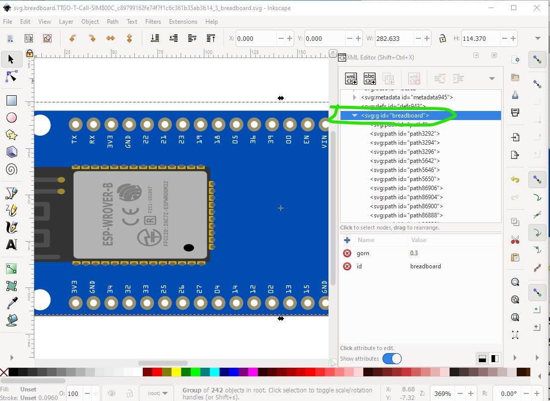
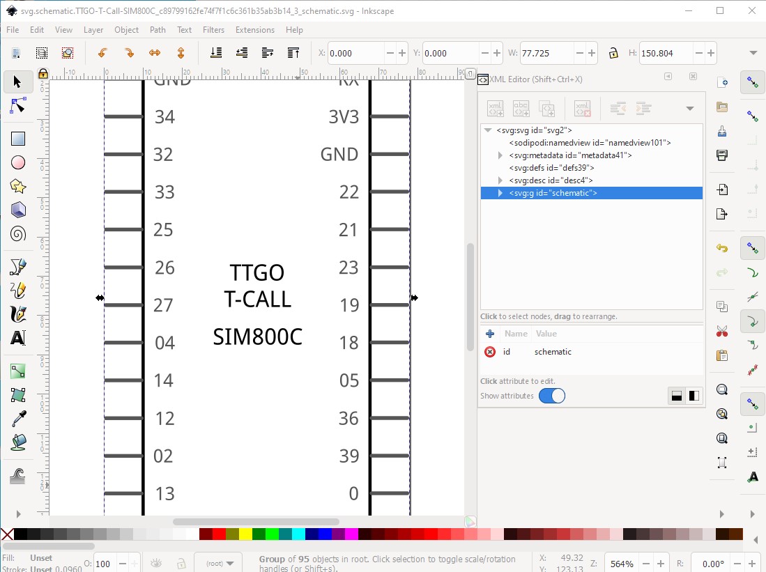
By and large fine, a few problems though. Breadboard and schematic are missing layerIds (the only thing that does is make the part not export as an image) and the bus pins are incorrect.

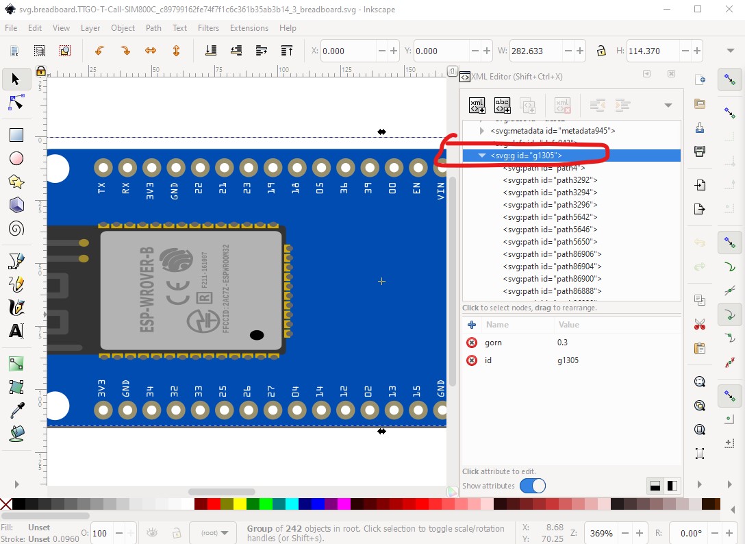
here just rename the first group breadboard

in schematic do a Edit->select all then group to create a group of the whole svg and then name it schematic.

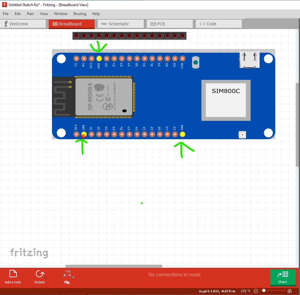
For the buses you need to determine the 3 GND bus pins and set them in to the bus in the .fzp file like this:

<bus id="GND">
  <nodeMember connectorId="connector1"/>
  <nodeMember connectorId="connector14"/>
  <nodeMember connectorId="connector26"/>
</bus>

which adds all the ground pins in to the bus so they all light if you click on any of them (as they are internally connected)

all changes are in this part. You will need to remove your current part (because I didn’t change moduleIds) then shutdown and restart Fritzing before it will let you load this one.

TTGO-T-Call-SIM800C-improved.fzpz (53.4 KB)

Peter

1 Like

Many thanks Peter for your check and the modifications!

I modified the PCB svg-file by editing it in a text editor so all layers / IDs are untouched (and correct). The other modification for breadboard and schematic was done in Inkscape. For editing I un-grouped the SVG and was not aware to destroy the neede structure. Thanks for this information. And I learned new details about the bus feature in Fritzing. Thanks again!