Hello microMerlin. Thanks for the reply. I think I did not explain my question very well. I need the breadboard view inverted.
I bought a dev board with the header pins already soldered in. So I need a part upside down from the part that I have.
I am a noob in Fritzing. I guess I have to draw my first part.
Thanks
If you have a part that you want inverted post the fzpz file and I will invert it for you. It is easy to do if you are familiar with part making (not so much otherwise …)
It does take a little initial research to learn the how a part is put together, but to simply flip the breadboard view is fairly simple. At a high level, starting from an existing part (fzpz) file:
in an empty folder, extract the separate files from the fzpz (unzip)
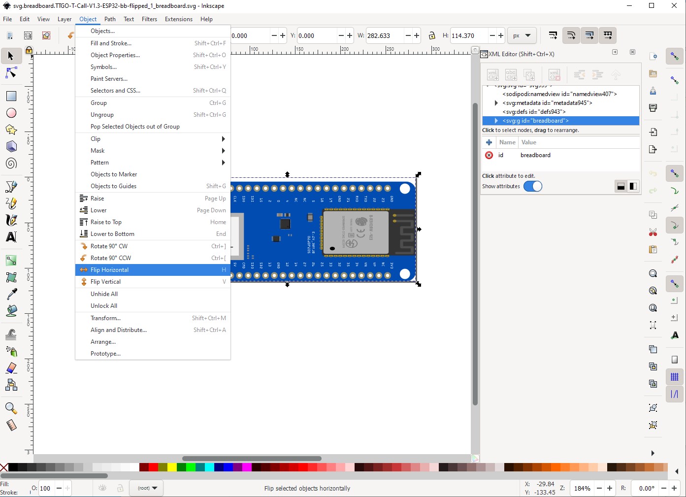
flip only the image for breadboard view (Inkscape)
combine the separate files back into a part file (zip) (use a different part file name)
load the flipped part in Fritzing
That would be enough if you did not want to have both the original and flipped versions of the part available in the bins at the same time. If you want both, add a step before combining the files
change module id in the fzp file (text editor, on windows, notepad would work)
If the part you want to flip is in core parts, it needs to be exported first, to create the fzpz file that my steps started from.
Any text in the breadboard view would also end up flipped with this.
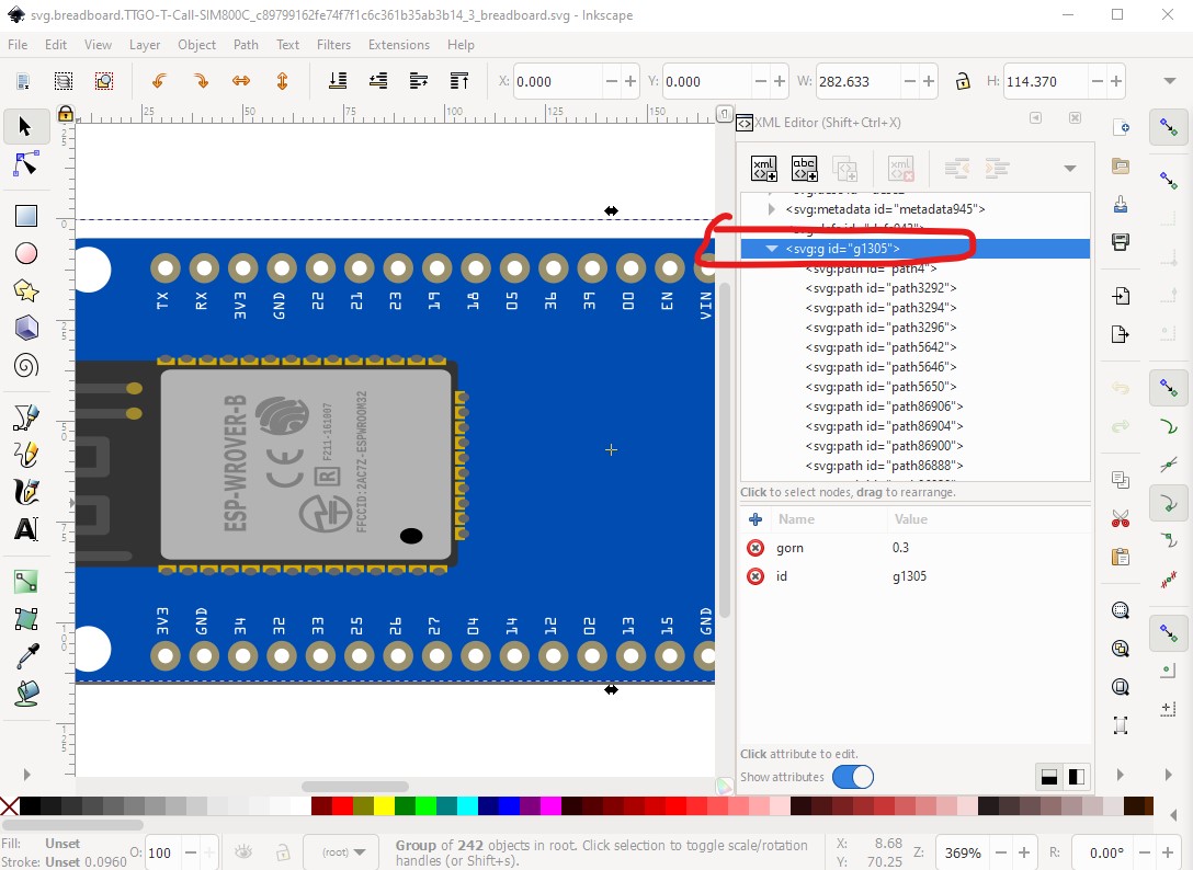
OK here is a new part that should do what you want. Here I edited the breadboard svg with Inkscape, did edit select all and Flip Horizontal (horizontal because that is how Frtizing pcb view is going to flip the board to the bottom of the board.) Then I selected the now backwards pin labels and flipped them vertical (which is technically wrong, but makes them readable.) and saved the svg.
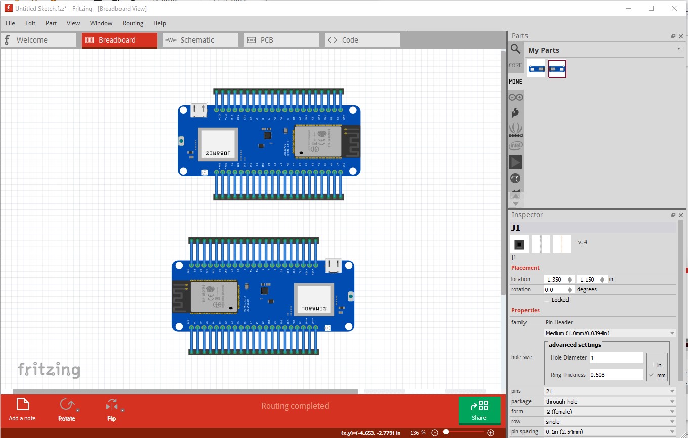
Then I changed the moduleId, family and file names in the .fzp file to make a new part which will load along side the original. In breadboard the new one (the top one) is viewed from the bottom of the board. The original part is on the bottom of the image. The labels on the chips are still backwards and unreadable, only the pin labels were inverted.
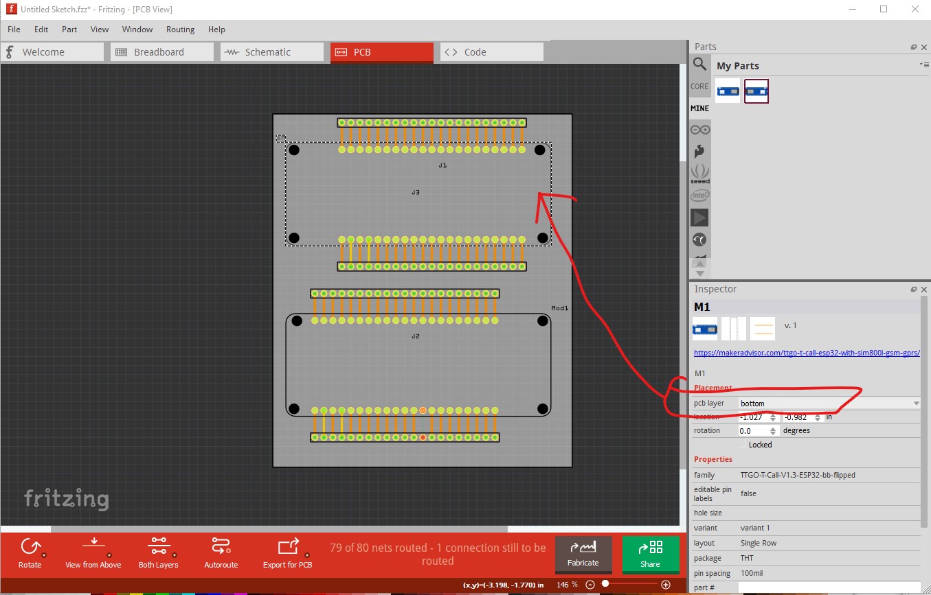
pcb has a quirk in that you need to change the pcb layer field in Inspector (the lower right window) from top (which is the default) to bottom so the pcb orientation will match that of breadboard and then install the actual module on the bottom of the pcb so the pins are correct. If you use a module with the pins the other way, you can leave pcb the way it is (pcb layer field set to top) and mount the module in the top of the board as usual.
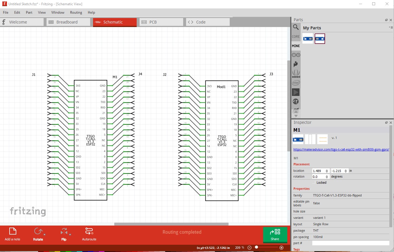
In pcb we don’t normally add pin names because you need to modify the part to remove them. If you want pin names you can drag the text icon in to pcb view in the sketch and add them.
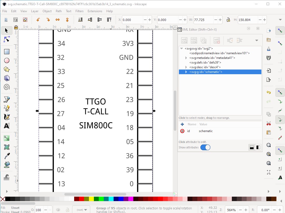
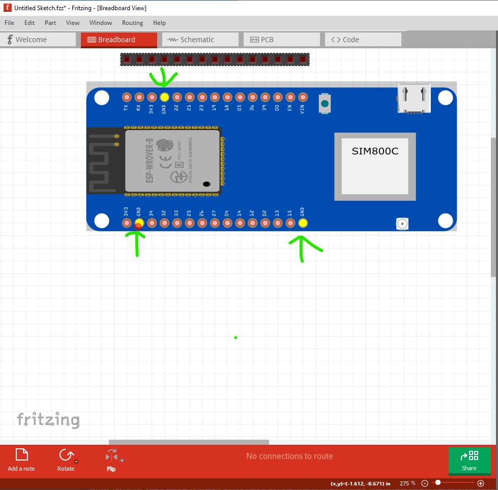
In the meantime different board variants from the TTGO T-Call are available. Also a T-Call with a SIM800C module and an AXP192 (instead of the ugly IP5306) power management chip. The SIM800C version has less pins and a different pinout. So I tried to adapt the Fritzing part above to the C-Version:
TTGO-T-Call-SIM800C.fzpz (54.6 KB)
[do not use this Fritzing part but the improved version from Peter in the next posting]
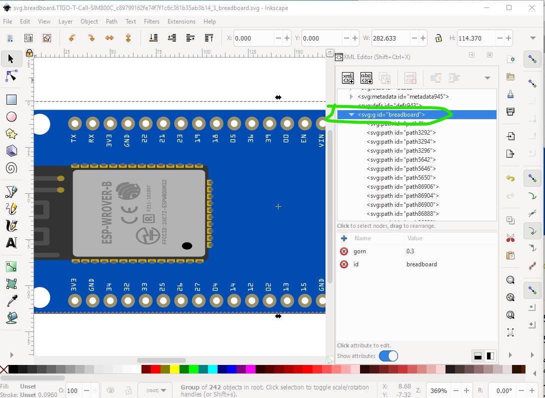
By and large fine, a few problems though. Breadboard and schematic are missing layerIds (the only thing that does is make the part not export as an image) and the bus pins are incorrect.
all changes are in this part. You will need to remove your current part (because I didn’t change moduleIds) then shutdown and restart Fritzing before it will let you load this one.
Many thanks Peter for your check and the modifications!
I modified the PCB svg-file by editing it in a text editor so all layers / IDs are untouched (and correct). The other modification for breadboard and schematic was done in Inkscape. For editing I un-grouped the SVG and was not aware to destroy the neede structure. Thanks for this information. And I learned new details about the bus feature in Fritzing. Thanks again!