I submitted a job to Aisler with the Fritzing files and they seem to be having a bit of a problem getting me a quote and asked if I could convert the files to any of the following:
I saw that you are working with Fritzing, currently there are always problems with Fritzing, do you have the possibility to switch to another design tool for example:
Altium: Push to AISLER

KiCad: .kicad_pcb or .brd

Autodesk Eagle: .brd

Autodesk Fusion 360: .brd

Target 3001: .t3001

LibrePCB: .lppz
Is this as easy as importing the Gerber files into the software? Or is this something that needs doing?
I believe (but don’t know of sure) that you would have to convert your sketch to one of the other packages. I don’t know of any automated tools to do so, so it would likely be a manual conversion (and thus a fair amount of work involving learning the alternate package.) The gerber files are presumably where the problem is since that is the output for Fritzing. There was a post somewhat recently about path curves in Fritzing being implemented by thousands of short lines which seemed to be causing problems with Aisler. The only solution to that would presumably be a Fritzing code change or a manual edit of the gerber files (neither of which are likely easy!)
I don’t know whether or not this comment is relevant in this case, but I have had problems in the past when submitting gerber files that are not named in accordance with the fabricators requirements. If that’s all that’s going on here, it may be as simple as renaming the gerbers in the required format.
As perter (@vanepp) mentioned I had issues to export rounded angle PCB. Fritzing does not convert that to an efficient shape in Gerber format (harder to manufacture and so more expensive). Arcs are converted to a long list of small points (thousands). So the manufacturer need to cut super fined grained segment, which requires advanced device (and might also take a looong time)
Otherwise, each time my boards weren’t imported by Aisler, that was due to a mistake.
I tried twice to import gerber file into KiCAD and Libre PCB (I work on Linux) it worked more or less straight forward. The main difficulties are in the target tools which are less user friendly.
Is it possible to edit the gerber file to replace the curves with arcs in either of those packages? I’m guessing this is @smilliken 's problem, but he didn’t specify the shape of the board he is trying to render. The other thing I have thought of (but haven’t tried and don’t know if will work) is replacing the beizer curves in the outline path fed to Fritzing with arcs by manually editing the path to replace the beizer curves with an arc. If that is done it is possible (but as I said currently untested) that Fritzing may replace the thousands of points (which may be needed to render a beizer curve) with a gerber arc command (I am assuming there is a gerber arc command, as I know very little about gerber format!) @microMerlin did this on a path I created for someone a while back, if I can find that post I may try rendering my (beizer curve) version of the outline and @microMerlin 's arc version and see if the gerber output is different or not. That may be an easy (or at least easier, as manual path editing is fairly hard!) solution to this problem. The outline I have done to date have beizer curves as the Inkscape path editor uses them (at least how I use it, it is more than possible I am using it wrong!) to make curves with the default settings.
edit:
@smilliken Could you please upload the svg you are using to make the board outline? If I’m testing, I may as well test on something that will be useful to someone and as far as I know the one of the fixes worked for the other poster.
edit2:
Nope, that doesn’t look to work. I grabbed the 2 svgs from this post:
and ran them both through Fritzing. They are basically identical with the curves formed via thousands of an inch steps in x to make the curve
my svg
G04 MADE WITH FRITZING*
G04 WWW.FRITZING.ORG*
G04 DOUBLE SIDED*
G04 HOLES PLATED*
G04 CONTOUR ON CENTER OF CONTOUR VECTOR*
%ASAXBY*%
%FSLAX23Y23*%
%MOIN*%
%OFA0B0*%
%SFA1.0B1.0*%
%ADD10C,0.008*%
%LNCONTOUR*%
G90*
G70*
G54D10*
X225Y1575D02*
X226Y1575D01*
X227Y1575D01*
X228Y1575D01*
X229Y1575D01*
X230Y1575D01*
X231Y1575D01*
X232Y1575D01*
…
micromerlin’s svg
G04 MADE WITH FRITZING*
G04 WWW.FRITZING.ORG*
G04 DOUBLE SIDED*
G04 HOLES PLATED*
G04 CONTOUR ON CENTER OF CONTOUR VECTOR*
%ASAXBY*%
%FSLAX23Y23*%
%MOIN*%
%OFA0B0*%
%SFA1.0B1.0*%
%ADD10C,0.008*%
%LNCONTOUR*%
G90*
G70*
G54D10*
X145Y1575D02*
X146Y1575D01*
X147Y1575D01*
X148Y1575D01*
X149Y1575D01*
X150Y1575D01*
X151Y1575D01*
X152Y1575D01*
mine is a 69K file and micromerlin’s is 68K so near identical in size and basically identical in format. So it looks like arcs in the path aren’t a solution here. I expect a Fritzing code fix is the only thing that will fix this (assuming there is a gerber construct that creates arcs which I don’t know if there is!)
Definitely looks like a Fritzing to Gerber limitation. This link is for Gerber X3, but other reading says that the section of interest (arcs) has not changed.
I agree, it looks to me like Fritzing could (but doesn’t currently) do this with a single D01 command that draws the arc from the start to the finish rather than by the current small increment method. This enhancement may be present in the gerber and image update pull request that was tried back around 2017, but turned out to have problems (and the folks that wrote it didn’t respond to emails requesting help) so it got backed out again. It is large though, some 6000 commits as I recall which should still be in the repo about the 0.9.3b level. The opinion at the time though was the author was more familiar with svg and image files than gerber (which may or may not be correct!) There also appears to be a free gerber editor available here
that perhaps could be used to manually modify the gerber file to make the curve a single arc from the start point to the end point. A python script may be able to do the same thing (assuming we can figure out the start and end points of the arc from the current Fritzing gerber file and figure out what the radius needs to be and how to specify it!) I expect this needs someone more familiar with the gerber format than I am however.
Thanks for the all of the info. I’ve been absent from the forum as I tried all of the programs Aisler suggested and I could not get the things to import/export properly. The closet was importing Gerber files into Eagle.
I reached back put to Aisler for any other solution and this is the reply I received yesterday.
unfortunately I don't know any other alternative how you can convert the data, we currently have no possibility to use data from Fritzing for the assembly service, sorry.

If you find a way to switch to another tool that we support, please let me know. Until then good luck with your developments.
I’ll head on over to Gerber and see about these things mentioned above.
I need the outline svg that you load in to the pcb via the load image file command (which should be just the triangle in green.) I probably have a copy of that already, but your current one would be better. I don’t see that this should be a problem though, it doesn’t have any curves it should (I think) create a fairly small contour.gm1 file.
edit:
I just tried the outline.svg file from Triangle_24-LED-v5.02_ws2812b
and it looks fine:
G04 MADE WITH FRITZING*
G04 WWW.FRITZING.ORG*
G04 DOUBLE SIDED*
G04 HOLES PLATED*
G04 CONTOUR ON CENTER OF CONTOUR VECTOR*
%ASAXBY*%
%FSLAX23Y23*%
%MOIN*%
%OFA0B0*%
%SFA1.0B1.0*%
%ADD10C,0.008*%
%LNCONTOUR*%
G90*
G70*
G54D10*
X1969Y3937D02*
X0Y0D01*
X0Y0D01*
X3937Y0D01*
X3937Y0D01*
X1969Y3937D01*
D02*
D02*
X1946Y2916D02*
X3225Y397D01*
X666Y397D01*
X1946Y2916D01*
D02*
D02*
G04 End of contour*
M02*
This is the svg that created the above file:
(note the edges of the triangle are not curved as some of the earlier versions are.) You may want to try using this svg to load the outline in to Fritzing and see if that fixes the problem. If you would upload the sketch that you are creating the gerber files from (the .fzz file) I’ll have a look and see if I can see anything that looks wrong (such as a new outline svg that isn’t correct!)
I will guess that is is not ONLY curves in pcb outlines that cause the problem. Curved traces probably do exactly the same thing. Or rounded corners in traces. The numbers I see in the example gerber output, which is stepping by 1 unit at a time, makes me think that this is using the same technique that I saw used for trace interference checking (DRC). That is, the board is render to a bit map image, then the pixels in that image are used to ‘trace’ the path that the tool needs to follow to cut the edge of the board or copper. It does not actually (directly) use the elements in the svg to calculate the gerber data. It is smart enough to remove the intermediate points in a straight line, but not to create a curve.
That is an assumption based on the symptoms seen, not by looking at the code.
Hello,
I’m maybe a bit late to answer.
Regarding bezier curve or not, my curves are arcs (‘a’ command in svg). I also looked a bit at the code, Fritzing translate svg command to gerber command but not all commands are supported.
We may have more chance using only polygon, polyline, rect, circle, line, ellipse shapes ; but no guaranty. I analysed a bit the code, but macro and function as parameter are difficult to follow.
Arcs seems converted to 8 more line cuts than lines.
Once it’s converted to gerber, there is no way to have one gerber shape…
I finally made a tool to convert arcs to a list of segment, and it worked for Aisler.
Don’t I remember one of these working with Aisler to successfully create boards in the past? If so I would suggest the place to start is with that version that worked and In that version make the changes you have done on the latest version. If Aisler can’t process that one, then at least we know where to look for the problem by comparing the version that worked to the version that does not to see what changes there are (we would need .fzz files from both versions to do that though!)
The whole reason this started was because I emailed the company wanting a better price for the Assemble Boards. I thought £250.00 plus was a bit too much for 3 boards. The measurements for my board was taken as 100mm x 100mm. But, this is a triangle that is no more than 12mm wide all the way around. I felt there must be a cheaper way if they looked at. Then emails came back saying they could not use the Fritzing output. Kind of disappointing.
I do have boards without the LEDs and capacitors to which I have purchased separately and just haven’t got to sitting down to install the parts. Maybe over the festive season.
While I have absolutely no experience in assembled boards, it is my sense this isn’t out of line. I think there is a high initial setup fee due to the time it takes to set up (and probably test!) the automated assembly. I think a run in the 1000s of boards to amortize the setup fee is usual, although they likely test the setup on a small number of boards at a high cost, although as I said I have no direct experience of this as I have never tried it! That will be especially true of Fritzing as the parts don’t have some of the attributes (such as center of gravity of the part) in the parts. I was told this 5 or 6 years ago by someone that used to (but no longer unfortunately does) post in the forums. He had run a pcb fab shop as well as knows a lot about Fritzing (I learned much of what I know about Fritzing from him) so I expect he knew what he was talking about. It was pointed out to me a little while ago that Fritzing does create a pnp.txt gerber file for pick and place which I assume then needs to be manually edited (which will likely be expensive as it needs someone skilled to do the work!) to add the necessary information (and implies that they have the necessary information for the parts!) so I’m not surprised that it is expensive for small numbers of boards. It is my sense that automated assembly is mostly useful for board runs in the 1000s or larger due to the startup costs, but as I said I have no direct experience here.
Some of the other problems I had, were trying to find WS2812b LEDs. They came in 10 packs, or 50 packs or you purchased the whole reel. When trying to place 24 LED’s there is no way of specifying to use the 10 pack 8 times to cover the 72 LED’s for the 3 boards. And I was going to purchase a reel at £0.58. They just don’t have a very good assortment of parts options. Could be the Global problems out there and I understand there is a setup cost. 3 is not a lot of PCB’s but then looking to prototype some boards, not going to purchase 1000.
On another note, I took the svg file from the
and placed it into the newest board I have and re-adjusted the copper. Then uploaded it to Aisler and it too had the same issues with the inside 3 corners.
I would say from the size of the gerber file of only the contour.gm1 gerber file, that shouldn’t be the cause of the problem, as it doesn’t have the large number of small segements (which in turn may not be the problem in this case, as we don’t know what Aisler’s software is unhappy with. Could you upload the .fzz file for the project that was able to make boards from Aisler and the .fzz file for the one that just failed please? Looking at the .fzz files and the gebers they produce may (or may not ) tell me what is going wrong. It may be the problem is in another area of the board as @microMerlin suggested a few posts ago. Also making sure the latest board passes DRC in Fritzing would be a good bet if it hasn’t been done, as there may be another error that Fritzing is complaining about that is causing the problem. Without the .fzz files it is hard to make any useful comments.
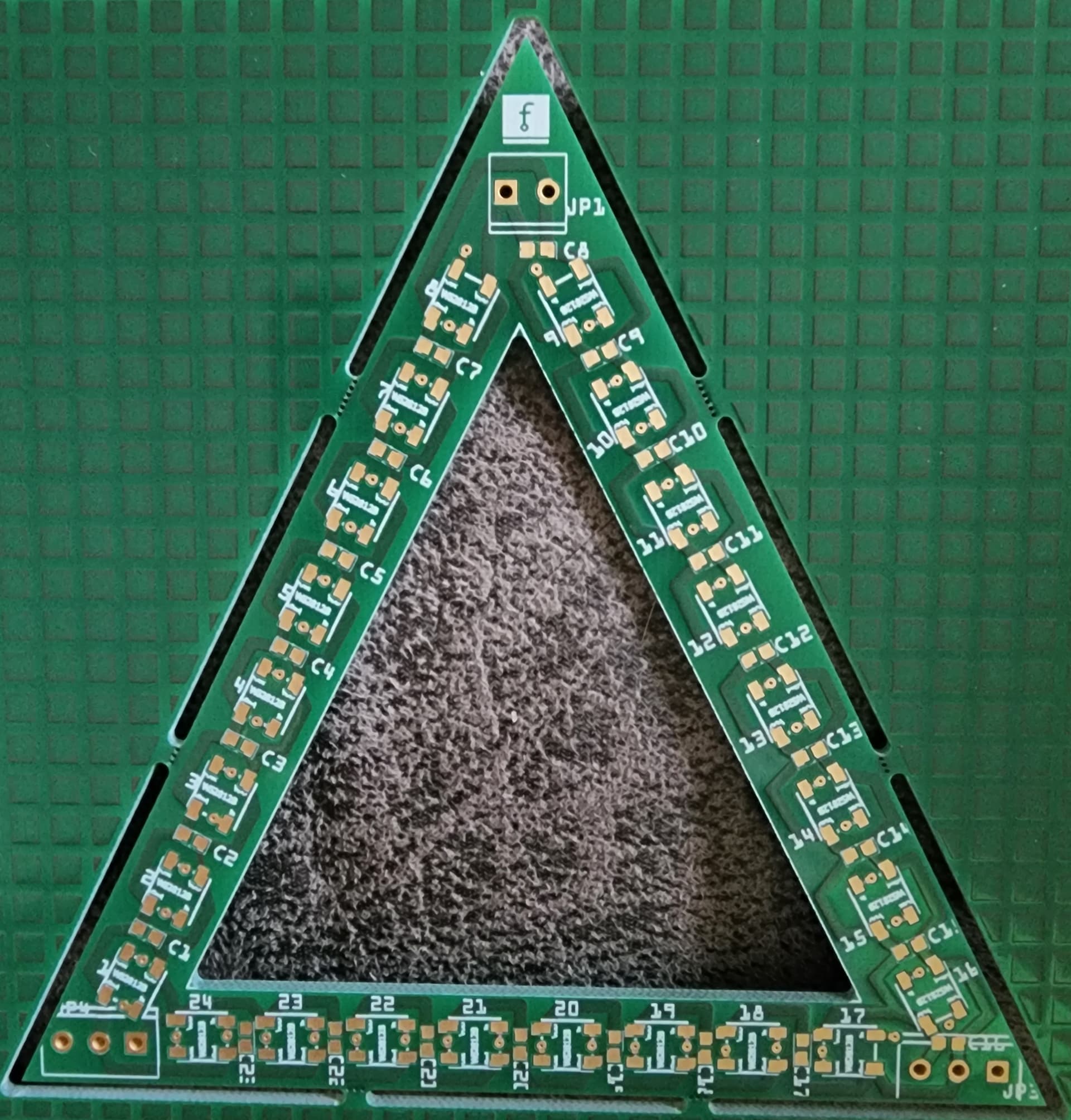
Triangle_24-LED-v8.01.fzz (94.1 KB)
This is the file that was uploaded to Aisler and which I ordered and received PCB’s and a stencil for the boards. Image below. I purchased the parts to place on the PCB’s from Digikey.ca.
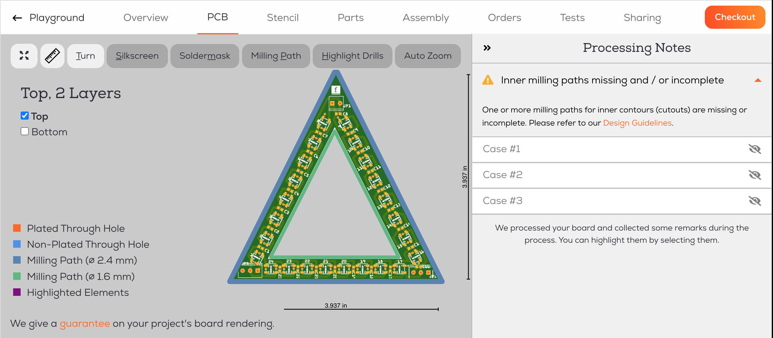
This file I just tried to upload to Aisler had received a problem with which is shown in the the attached below. Should be noted, this same error was received as well on the version 8.01 in which the boards were created.
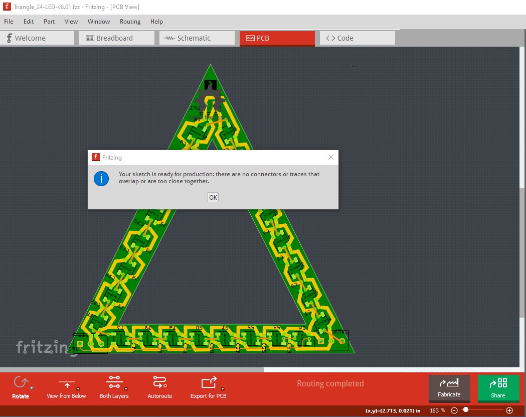
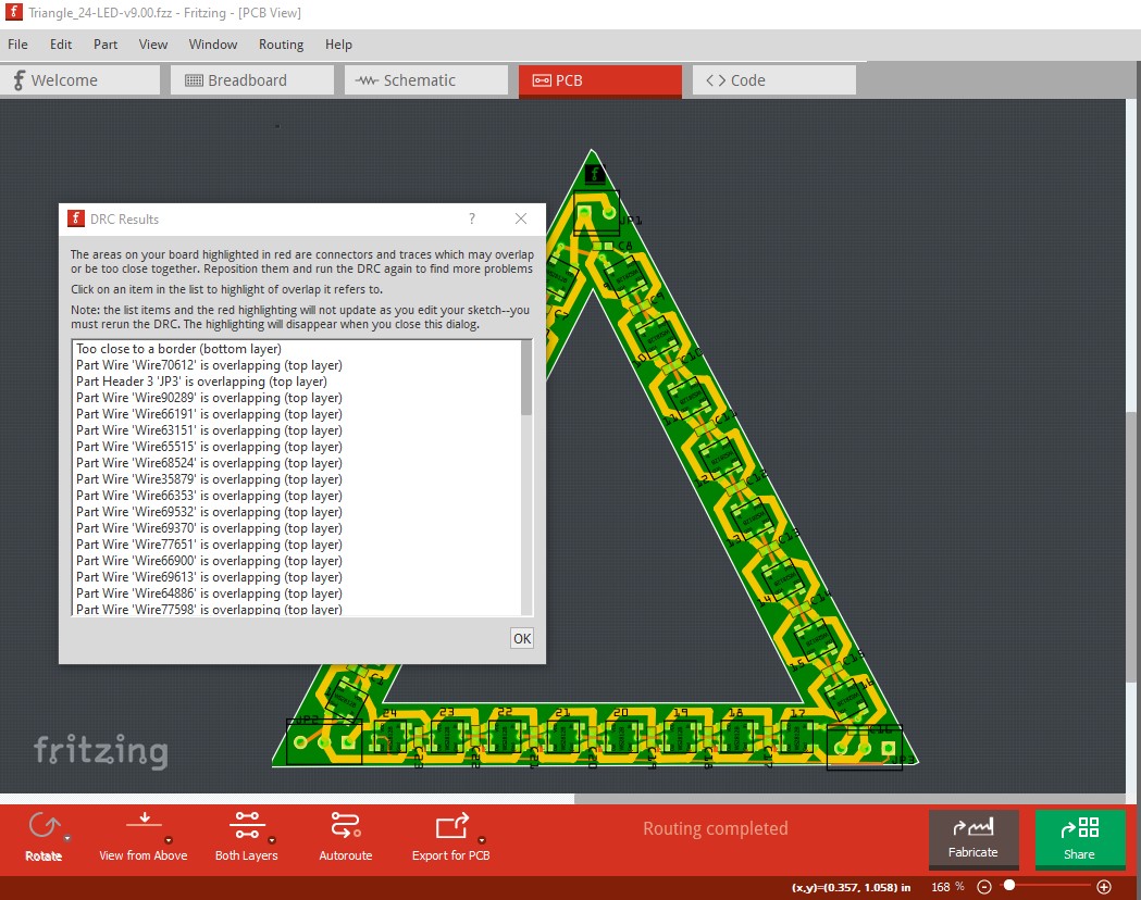
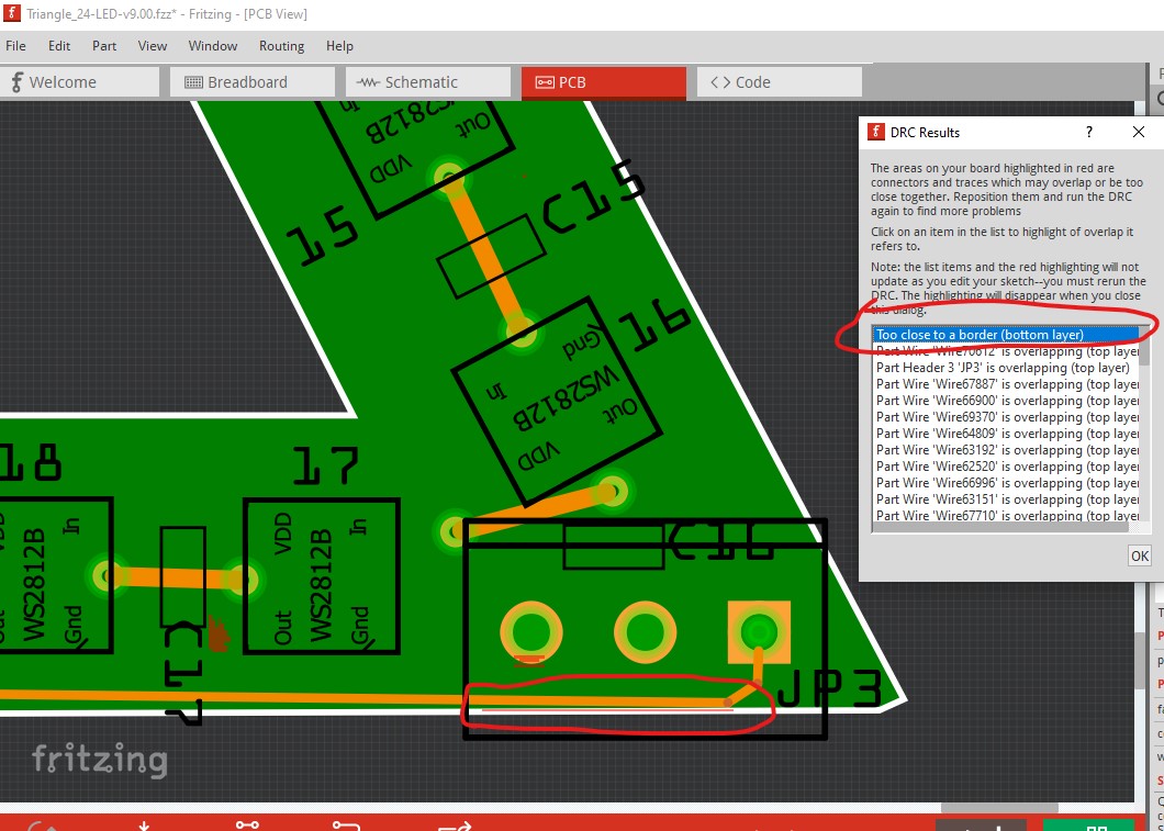
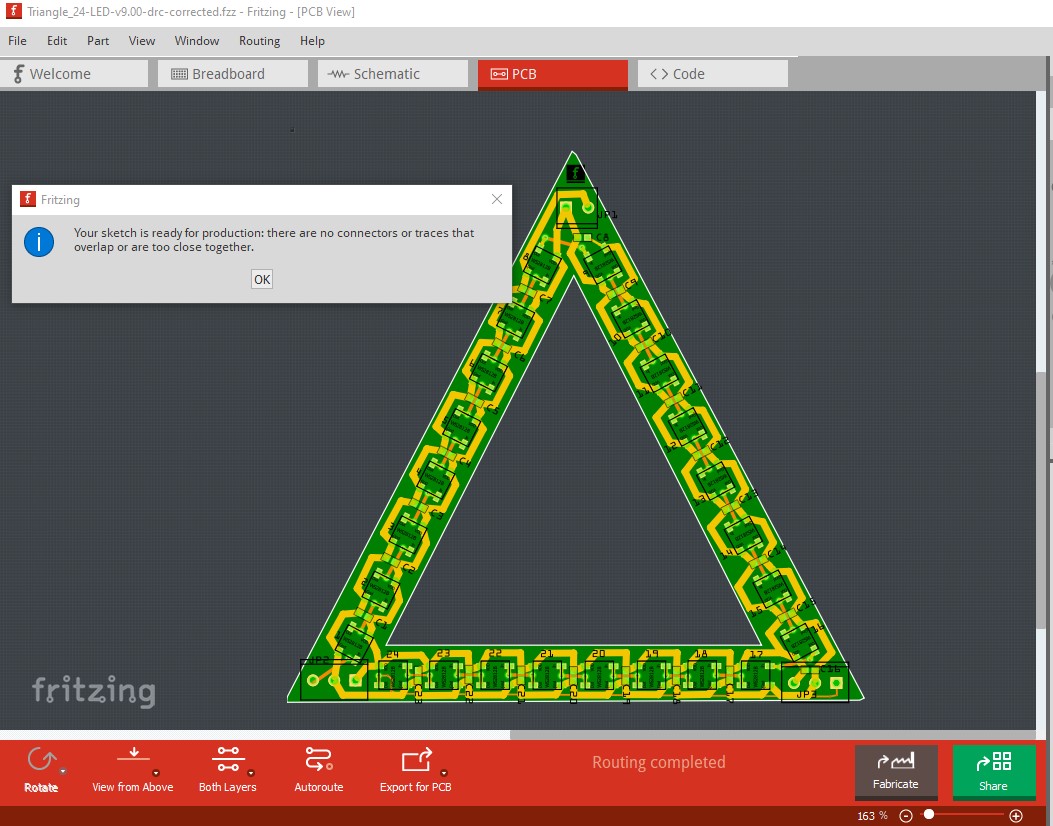
Initially this is easy, I’ll look closer to see if there is another problem as well. On Triangle_24-LED-v8.01.fzz DRC (Routing->Design Rules Check (DRC)) passes correctly:
which may well be what is causing the error messages (won’t know til I look over the DRC errors which I haven’t yet.) So they may be complaining (poorly I must admit, unless there is more information in the error reports that don’t show up in the screen shot) about traces being too close to the edge of the board causing a milling problem which we are incorrectly attributing to a bad outline.svg file. I’ll look it over and report back.
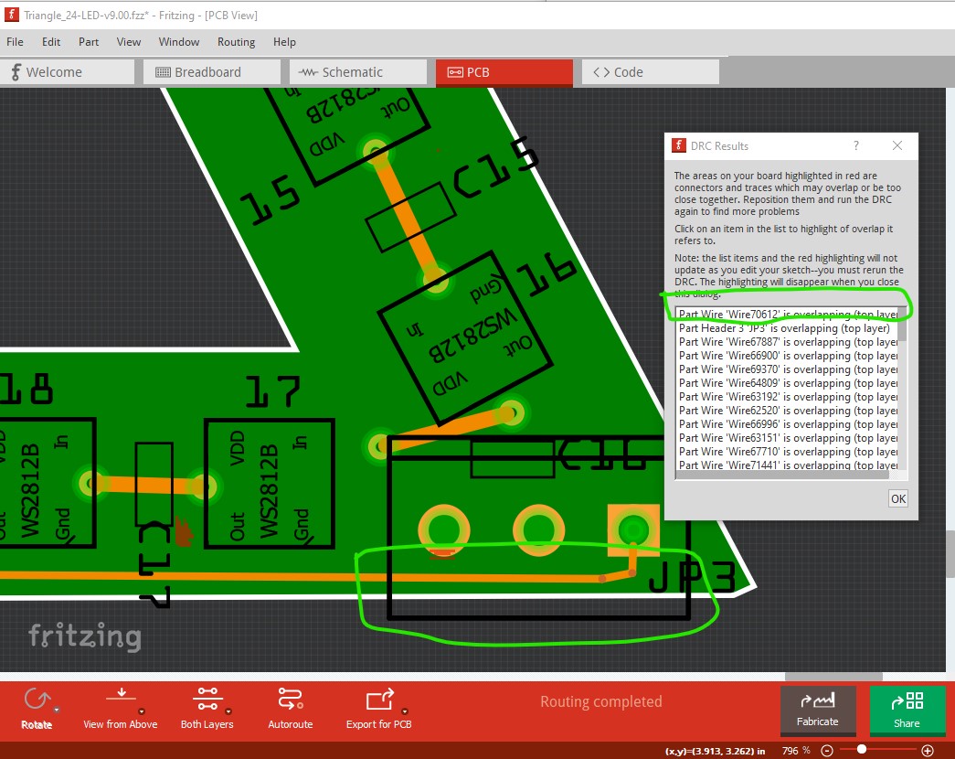
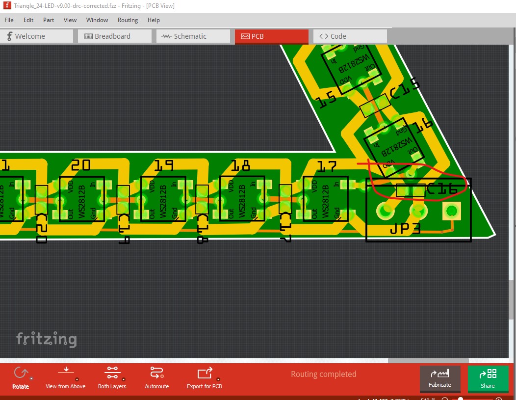
here the DRC message is gone and the trace is no longer too close to the edge of the board. The rest will be similar. While this won’t hurt anything, you can’t actually install C16 because it overlaps with the connector (assuming you mount the connector!) If you don’t mount JP3 then you can mount C16 which may be useful in some cases so I would leave this as is.
Here is a new copy of the corrected .fzz file which now passes DRC. Try this one and see if the complaints go away. This is why it is always most useful to upload the .fzz file of a board that doesn’t work, with the .fzz file we can poke at and correct things that are wrong!