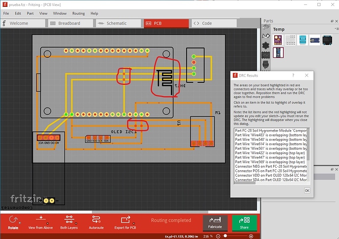
OK, a fair number of problems here. A number of them are because of poorly made parts though. First run DRC (Routing-> Design Rules Check) against pcb which indicates a number of errors:
The circled areas indicate problems. Traces on top or bottom layer can’t overlap. As this stands the traces circled in red are shorted together. As well the traces can’t go through the antenna area of the node MCU (they will affect the antenna on the board.) They should be easy to fix but many of the parts are poorly configured. I So to start replace the DHT11 part with the Humidity and Temperature Sensor DHT11improved.fzpz from here
which is better than the one in core parts (and in this sketch!) Replace the FC-28 part with this one:
FC-28 Soil Hygrometer Module-improved.fzpz (7.9 KB)
because the one in the sketch is broken. The OLED display part is also broken so replace it with the OLED-128x64-I2C-Monochrome-Display-GND-VDD.fzpz
part from here:
In addition double check that this is the board you have. As noted there are two common boards but with opposite pin configurations for power. If you have the other module, connecting it to the wrong Fritzing part will likely destroy it! For the bmp280 part use the one from here
as the one in your sketch is broken and won’t route on the bottom layer. This sketch has all the part substitutions made and contains all the corrected parts mentioned above.
prueba-improved.fzz (132.4 KB)
However one last point. How is the node MCU being powered? If the USB connector is connected, it will get power from USB. But if USB isn’t normally connected you need to supply a power source to the raw input pin for this to work. I would also suggest wiring this on the breadboard and checking that it actually works properly before ordering boards.
Peter
